Cub Cadet TANK S Series: Electrical System User Manual
Page 5
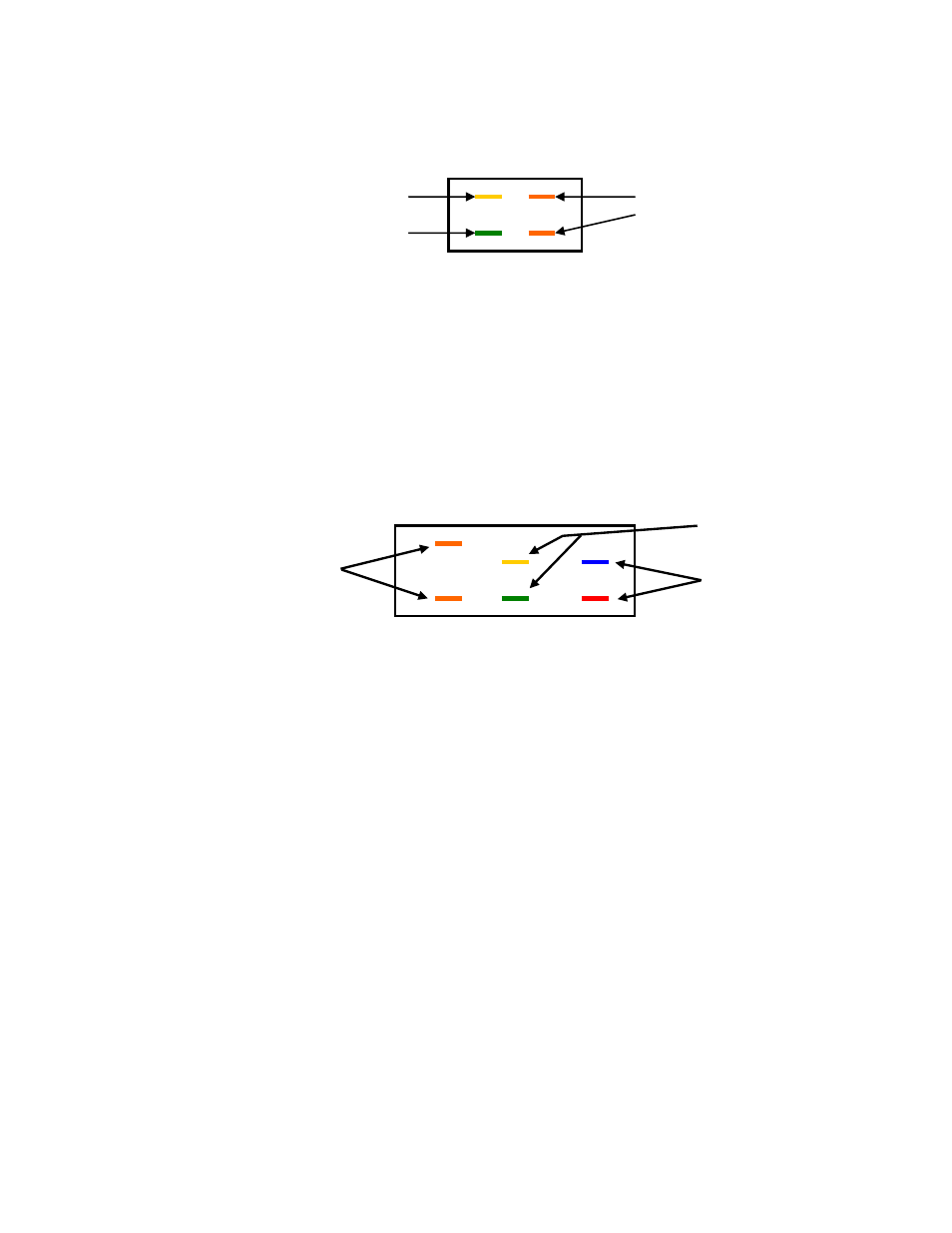
BRAKE SWITCH:
This is a manually operated safety switch. When the brake is in the engaged position, switch button
in, the orange wire (starter circuit) is closed allowing current to pass thru from the ignition switch.
The circuit between the green ground and yellow (magneto) is open. With the brake disengaged,
the open and closed circuits are reversed.
Yellow Wire to Relay (87a).
Orange from Ignition Switch to
Closed to Ground, Brake Off
PTO Switch. Open Circuit when
Brake is Off
Green Ground to Yellow w/
Brake Off.
PTO SWITCH:
A manually activated switch to provide current (+) to the PTO clutch with provisions to regulate the
starter and magneto circuits. With switch in the off position, orange circuit (starter) is closed. The
green (ground) to yellow (magneto) circuit and red (+) to blue (PTO clutch) are open. This allows
the current to flow to the starter.
When the switch is engaged, the orange circuit (starter) is open , green (ground) to yellow
(magneto) is closed and red (+) to blue (PTO clutch) is also closed. This disables the starter circuit
and enables the PTO clutch to engage. The closed or grounded magneto circuit which normally
would shut the engine down is opened at the relay via the seat switch which brakes the ground
circuit to the engine.
View From Contact End
9 5
4
Yellow Pole (5) &
Green Pole (2). Open
Orange: To Starter Solenoid
when Switch is off.
9 + 3 Circuit Closed when
Switch is off. Allows Eng.
Red +(1) & Blue (4)
Solenoid to Activate.
Closed Circuit when
switch Is on Activating
3 2-5 1-4
the PTO Clutch.
WIRE HARNESS:
The main wire harness is common for all AIR COOLED ENGINES. It is configured to match a
Kohler Engine internal starter solenoid and supply plug. The same harness is used for Kawasaki
Engines by adding a short “pig tail” to the engine plug matching the Kawasaki wire group and leads
to supply the external starter solenoid.
The TANK-S Unit has a hydraulic oil cooling system incorporating a heat exchanger and cooling
fan. The fan circuit is a red wire tied into the positive circuit at the engine voltage regulator and
grounded to the engine block. The fan is activated when the ignition key switch is turned on.
EFI, DFI, COMPUTERIZED ENGINES as Kawasaki Horiz.. Liquid Cooled use the same basic wire
color-coding. But, because of the computer, fuel pump and indicator lights, 2 relays and 1 fuse
have been added to feed and protect these additional components.
The DIESEL UNIT wire harnesses are unique to that unit. The engine is shut down thru positive (+)
current not magneto grounding as a gasoline engine. Because of the many supportive components
as indicator lights, cooling fan, glow plugs etc. additional fuses and relays are incorporated in the
system.
The PTO CLUTCH can generate current that can feed back into the system. The current spike can
damage components as relays and computers. Units with EFI, DFI and Diesel engines have a
diode in the circuit supplying current to the clutch.
Consult the wire diagram for detail routing.
5 of 8