Danger, Warning – Cub Cadet 7 Fabricated Deck User Manual
Page 20
20
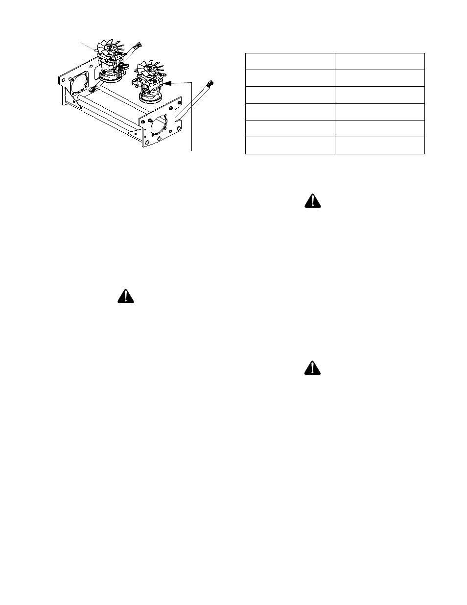
caps and drain oil from both left and right
pumps. Replace and retighten nuts.
Figure. 10
Hydraulic
pumps
Unfasten hose and drain from
this side of both pumps.
j.
Remove the three screws from the top of the
oil filter and replace the oil filter element. Coat
the sealing surface with Shell Rimula 15W40
oil or equivalent. Install the three screws back
into the oil filter.
k.
Add proper amount of hydraulic oil to reser-
voir. Use Shell Rimula 15W40 or equivalent.
l.
Run and purge gearboxes. Check oil level.
m. Add proper amount of hydraulic oil to reservoir
and repeat step L.
D.Electrical Circuit
Danger:
Read General Safety Precautions Nos. 9 and 10.
1.
Battery: The battery is located beneath the oper-
ator’s seat. Remove the fillcaps and check the
level of the liquid electrolyte in the battery every
50 operating hours. If the level in any of the six
cells has dropped below the bottom of the split
ring inside the fill hole, refill the cell with distilled
water. To keep the outside of the battery clean,
brush on a strong solution of bicarbonate of soda
and water and rinse with clean water. Keep the
contacts and cable ends clean with a wire brush
and make sure the connections are tight. Coat
the terminals with petroleum jelly to prevent cor-
rosion.
2.
Battery Storage: When storing the Mower for
long periods of time the following guidelines
should be taken.
a.
Disconnect the battery cables from the termi-
nals and remove the battery. You will have to
remove the control panel to access the battery
strap. Replace control panel.
b.
Clean the battery before storing. A dirty bat-
tery will lose its charge over time.
c.
Store the battery with a full charge. A dis-
charged battery will freeze (refer to the table
below).
Specific Gravity
Freezing Temp (°F)
1.265
-71
1.250
-62
1.200
-16
1.150
5
1.100
16
d.
Recharge battery when ever the specific grav-
ity value is less than 1.225
3.
Battery Removal
Warning:
When removing the cables from the battery follow
these steps to avoid a short between the wrench
and the frame.
a. Remove the Negative (black) cable.
b. Remove the Positive (red) cable.
c.
Release the hold down straps.
d. Remove the battery without tipping.
4.
Installing the Battery
Note:
The battery is delivered from the factory
fully charged and filled with electrolyte.
a. Attach the Positive (red) cable.
b.
Attach the Negative (black) cable.
c.
Attach the rubber battery strap.
5.
Jump Starting
Warning:
Note:
For E.F.I. Tanks, the battery must be dis-
connected (Negative lead) for storage exceeding
four weeks. Do not “Jump Start” an E.F.I. unit,
recharge or replace battery to avoid damage to
the Electronic Control Unit (ECU).
Failure to use this starting procedure can cause
sparking, and the gases in the battery to explode.
a.
Attach the end of the red jumper cable to the
Positive terminal (+) of the charged battery.
b.
Attach the other end of the red jumper cable to
the Positive terminal (+) of the low charge bat-
tery.
c.
Attach the end of the black jumper cable to the
Negative terminal of the charged battery.
d.
Attach the other end of the black jumper cable
to the frame of the unit with the low charge
battery.
6.
Fuses: There is one fuse located in the wiring
between the ignition and start switch and other