Setup of the dome camera – COP-USA CD52W-NV User Manual
Page 4
Operation Manual for Intelligent Speed Dome Camera
h. Zero Illuminance: it is used only when the external brightness is extremely low.
Normally the camera works on the automatic state. In case the external brightness is
lower than 1Lux, the camera can be switch to the Zero Illuminance state automatically
and icon appears on the screen. You can also set the Zero Illuminance state
manually.
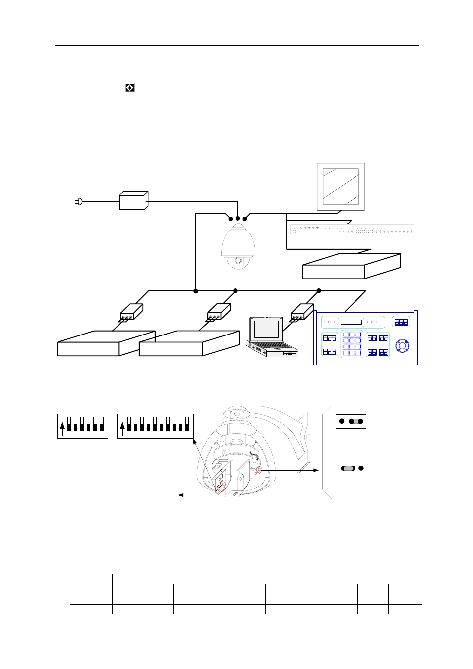
Ⅲ. Setup of the Dome Camera
1. Connection of the System
1) The Systematic Drawing of the Dome Camera
Power Adapter
AC24V OUT
AD Matrix
B S W
RS232
B S W
Philips Matrix
Protocol Adapter
Protocol Adapter
Code Converter
RS-485
RS-485
RS-485
RS-485
Matrix
AC90~AC260V Input
Multiplexer
RS
-4
85
Power IN
VIDEO OUT
C
V
Monitor
Dome Camera
Figure 1
2) Address / Protocol Coding Switch Drawing
ON
1
2
3
4
5
6
SW2
ON
1
2
3
4
5
6 7
8
9 10
SW1
Protocol Set
Address Set
Bracket for fixed camera
SW2: DIP1--DIP4 Select Protocol
SW2: DIP5--DIP6 Select Baud Rate
JP
3
1 2
3
1 2
JP
120Ω term inal resistor is
opened forR S485 bus
120Ω term inal resistor is
connected on R S485 B us
Figure 2
2. Setup of Coding Switch of Dome Camera. As shown in Figure 2, SW1 is used to set
address of the dome camera from 1 – 1023. The ID-CODE from DIP-10 to DIP-1 are
equivalent to a 10-bit binary digit. DIP-10 is MSB while DIP-1 is LSB. The state “ON” of
each bit means 1 while “OFF” means 0. Following table shows states of coding switches
of some addresses.
ID-CODE Status
Dome
Address
DIP-1 DIP-2 DIP-3
DIP-4
DIP-5
DIP-6
DIP-7
DIP-8 DIP-9 DIP-10
1
ON OFF OFF OFF OFF OFF OFF OFF OFF OFF
2
OFF ON OFF OFF OFF OFF OFF OFF OFF OFF
3