Checkline DT-326 User Manual
Page 21
18
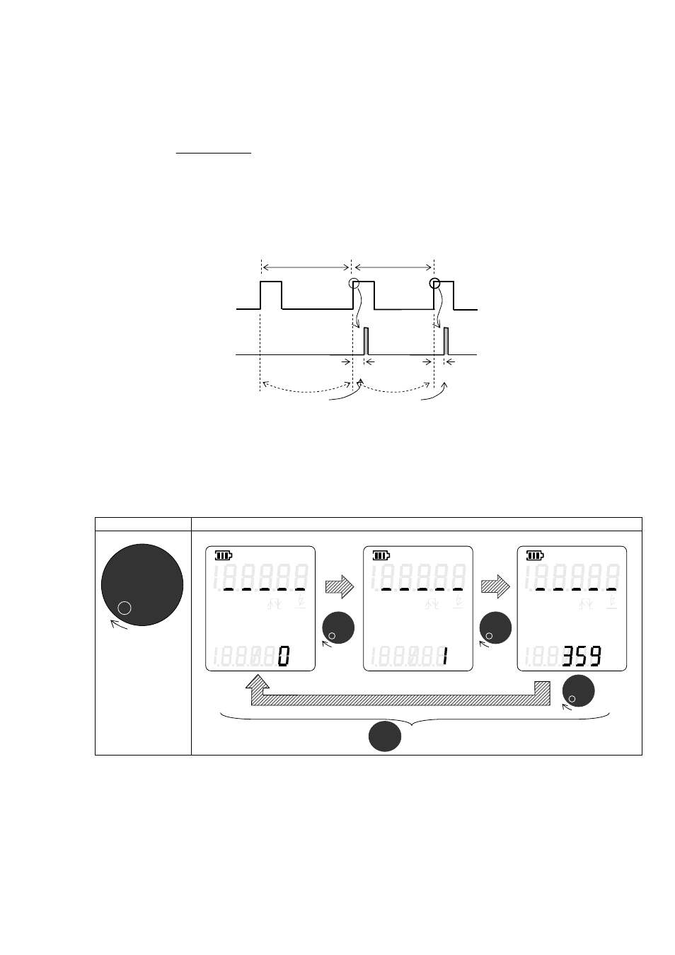
4.4.2.2 “Delay angle” setting
Set the delay angle from 0° to 360° in 1° increment s.
The actual delay time is as follows:
While the DT-326 does not flash at the 1
st
trigger pulse as shown below in the timing chart.
[Example]
Trigger: Positive edge
Delay angle: 36°
If the frequency of the external trigger input changes, the timing of the flash is inaccurate, because the timing is
calculated based on the previous measured period.
If the current period of external trigger input is less than the previous period and the next trigger input occurs
before the flash time, the delay angle setting is ignored and the unit flashes at delay angle = 0°.
Delay angle increases as the dial is rotated to the right. The angle settings will go to 0° when angle is past 359°.
Operation
Expression
Turn clockwise
Auto Range
Trigger
Edge
Delay Deg
Flash Time
Ave Last Min
Max
min
sec
h
Hz
○
○
○
○
ms
Auto Range
Trigger
Edge
Delay Deg
Flash Time
Ave Last Min
Max
min
sec
h
Hz
○
○
○
○
ms
Auto Range
Trigger
Edge
Delay Deg
Flash Time
Ave Last Min
Max
min
sec
h
Hz
○
○
○
○
ms
Go to delay time setting
Delay angle setting
360°
× Period of External Input + approx. 60us (Built-in)
PHASE+
External Pulse
Input
LED Flash
100ms (360°)
10ms (36°)
Delay
80ms (360°)
8ms (36°)
Delay
Measure
frequency
Measure
frequency