Alyseum ALeX User Manual
Page 8
ALeX – User’s manual © - Revision 1.7
Page 8
4.4.7
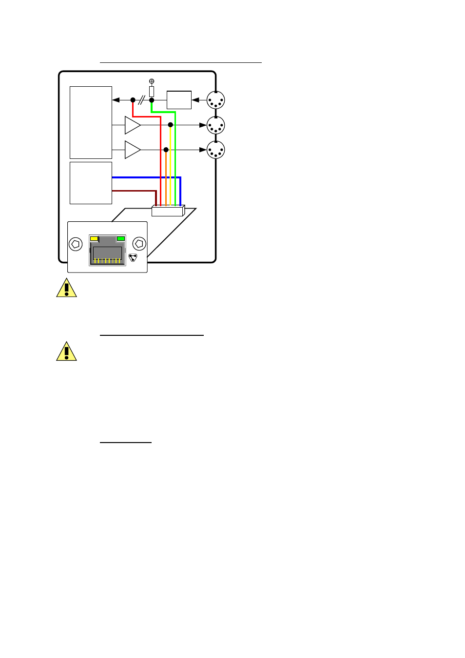
Schematic for 1 MIDI In and 2 MIDI Outs
MIDI Out 1
MIDI Out 2
Opto
App.
UARTs
R
LK/ACT
ALYSEUM
ALeX
App.
Power
5V to 18V
GND or 0V
MIDI In
Input & Output voltage ratings: 3.3V to 5V (1 logic) and 0V (0 logic)
4.4.8
Power supply connection
Mistakes in the wiring of the supply may destroy the ALeX module and the power supply of
your equipment
Check with a Voltmeter the supply voltage inside the equipment. Try to locate the Digital
positive between 5V minimum and 18 V DC maximum, and connect it the blue wire.
Do not forget connecting the brown wire to a Digital 0V/ground point on the PCB.
4.4.9 Powering
up
● Reread and check carefully all the installation steps.
● The LED should flash briefly as you switch on the supply of your equipment.
● Connecting an active network cable should make the Network LED blink according to
the traffic.