Som 6 si, Installation, 1 mounting – STIEBEL ELTRON SOM 6 SI User Manual
Page 4: 2 electrical wiring
SOM 6 SI
© 06184 som_6_si.monen.ind
d
|
4
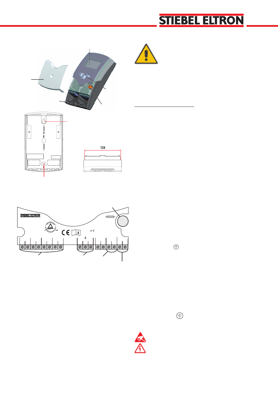
display
pushbutton
can fuse 4A
cable conduits with strain
relief
cover
1
2
S1
S2
S3
3
4
5
6
Temp. Sensor Pt1000
L
N
R1
N
20
19
18
17
14
13
12
2 (1) A 115 V~
T4A
US-West Hatfield, MA 01088
SOM 6 SI
Inc.
1.1 Mounting
The unit is designed for indoor installation only. It is not
suitable for installation in hazardous locations and should not
be sited near to any electromagnetic field. The controller
must installed in accordance with all electrical regulations.
These regulations vary from region to region. Please contact
the appropriate agency in your area if unclear on this.
Wall Mounting Instructions
1. Unscrew the cross-recessed screw of the cover and
remove it from the housing.
2. Mark the upper fastening point on the wall and mount
the enclosed dowel and screw.
3. Hang up the housing at the upper fastening point and
mark the lower fastening point on the wall. The distance
between the 2 mounting holes is 130 mm.
4. Fasten the housing at its lower point..
1. Installation
Warning!
Switch-off power supply before
opening the housing.
1.2 Electrical wiring
The power supply to the controller must only be made by
an external power supply switch and the line voltage must
be 120 VAC (50/60 Hz). Flexible lines are to be fixed at the
housing by enclosed strain relief supports and screws.
The SOM 6 controller is equipped with 1 relay which is
usually connected to the solar loop’s circulator pump.
• Relay 1
18 = Conductor R1
17 = Neutral conductor N
13 = Earth ground
The temperature sensors (S1 to S4) are to be connected
to the following terminals (not polarity sensitive):
1 / 2 = Sensor 1 (Collector sensor)
3 / 4 = Sensor 2 (Storage sensor)
5 / 6 = Sensor 3 (For monitoring only)
7 / 8 = Sensor 4 (For monitoring or Energy Production
Measurement)
The power supply is to be connected to the following
terminals:
19 = neutral conductor N
20 = line conductor L
12 = ground terminal
Line voltage input
fuse
Relay output
Sensor clamps
Upper fastening hole
Lower fastening hole
Earth ground
Electrostatic discharge can lead to damage to
electronic components!
Hazardous voltage present!
S4
7 8