Rear panel, U.s. & canadian models only, Typical configurations – Yamaha Q2031A User Manual
Page 6: Insertion in the main line of the output system
Attention! The text in this document has been recognized automatically. To view the original document, you can use the "Original mode".
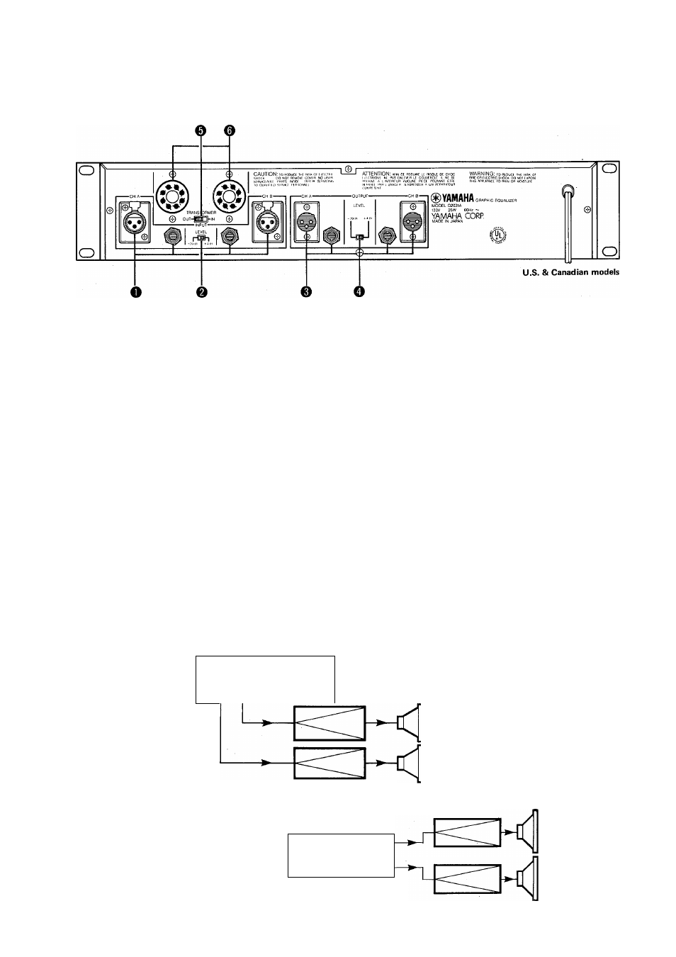
REAR PANEL
O
INPUT Connectors
Both balanced (3-pin female XLR type connectors) and un
balanced (1/4” phone jacks) input connectors are available.
A 600 ohm line should be used for both. Use the INPUT
LEVEL switch to set the rated input level to either
+4
dB or
-20 dB.
©INPUT LEVEL Switch
Use this switch to set the rated nominal input level to corre
spond to the rated output level of the equipment to be
connected.
0 OUTPUT Connectors
Both balanced (3-pin male XLR type connectors) and un
balanced (1/4” phone jacks) output connectors are available.
A 600 ohm lines should be used for the balanced XLR’s and
a 10k ohm line for the unbalanced 1 /4” phone jacks. Use the
OUTPUT LEVEL switch to set the rated nominal output
level to either
+4
or —20 dB.
©OUTPUT LEVEL Switch
Use this switch to set the rated nominal output level to
correspond to the rated input level of the equipment to be
connected.
U.S. & Canadian models only
©TRANSFORMER In/Out Switch
This switch inserts the optional (See item ©) Input
Transformers into the input stage, bypassing internal
electronic balancing.
©Input Transformer Octal Sockets
Two Octal Sockets are provided to accept optional
15k to 15k ohm bridging Input Transformers. (BRT15K)
©Internal Output Transformer (Optionals)
The Output Transformer should be installed by a quali
fied service technicians.
TYPICAL CONFIGURATIONS
Insertion between the channel (master) insert out/in
MIXING CONSOLE
INSERT OUT
OUTPUT
L R
INSERT IN
02031A
POWER AMPS
Insertion in the main line of the output system
MIXING CONSOLE
CH A INPUT
CH A OUTPUT
SPEAKERS
POWER AMPS
SPEAKERS
OUTPUT L
OUTPUT R
Q2031A
CH A
CH A
INPUT
OUTPUT
CH B
CH B
INPUT
OUTPUT