Note – Yamaha pw80 User Manual
Page 37
Attention! The text in this document has been recognized automatically. To view the original document, you can use the "Original mode".
If beyond tolerance replace piston or rebore
cylinder as required.
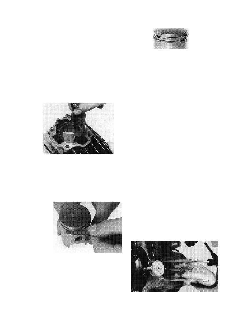
Piston rings
1. Remove ring from piston.
2.
Insert ring into cylinder. Push down ap
proximately 20 mm (0.79 in) using piston
crown to maintain right-angle to bore.
Measure installed end gap. If beyond
tolerance, replace.
Ring end gap installed (top and 2nd):
0.15-0.35 mm (0.006-0.014 in)
3.
With rings installed in grooves, insert
feeler gauge between ring and groove. If
beyond tolerance, replace ring and/or
piston as required.
Ring groove clearance:
0.020-0.060 mm (0.0008-0.0024 in)
4.
5.
Holding cylinder towards light, check for
full seating of ring around bore. If not fully
seated, check cylinder. If cylinder is not
out-of-round, replace piston ring.
During installation, make sure ring ends
are properly fitted around ring locating pin
in piston groove. Apply liberal coating of
two-stroke oil to ring.
NOTE: ------------------------------------------
New rings require break-in. Follow first portion
of new machine break-in procedure.
Piston pin bearing and connecting rod
1.
Check the pin for signs of wear. If any
wear is evident, replace pin and bearing.
2.
Check the pin and bearing for signs of
heat discoloration. If excessive (heavily
blued), replace both.
3.
Check the bearing cage for excessive
wear. Check the rollers for signs of flat
spots. If found, replace pin and bearing.
4.
Apply a light film of oil to pin and bear
ing surfaces. Install in connecting rod
small end. Check for play. There should
be no noticeable vertical play. If play ex
ists, check connecting rod small end
diameter for wear. Replace pin and bear
ing or all as required.
5.
Mount the dial gauge at right angles to
connecting rod small end holding the bot
tom of rod toward the dial indicator, rock
top of rod and measure axial play.
Connecting rod axial play:
1.0 mm (0.04 in)
-25-