Major operating controls and their functions – Panasonic RAMSA WP-1400 User Manual
Page 4
Attention! The text in this document has been recognized automatically. To view the original document, you can use the "Original mode".
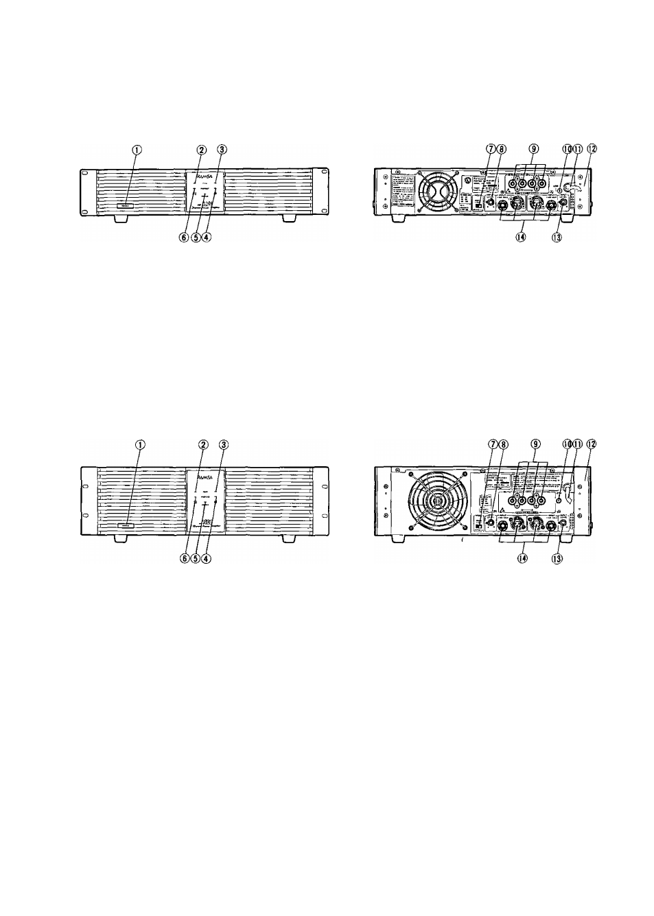
MAJOR OPERATING CONTROLS AND THEIR FUNCTIONS
WP-1200
• Front Panel:
• Rear Panel
WP-1400
• Front Panel
• Rear Panel:
1. Power ON/OFF switch [POWERJ
•
The
power
amplifier
reaches
the
operating
conditions 4 to 6 seconds after turning on the
power ON/OFF switch due to a muting circuit
which prevents switching noise at power-up.
CAUTION :
When using the WP-1200/1400 in a system
with other equipment such as a mixer, equalizer,
and other signal processor, always turn the
amplifier on last as switching noise from the other
equipment can damage the speakers. Similarly, at
system power-down always turn the amplifier off
first.
2. Peak level Indicator (PEAK (red) A]
When this LED lights, the output signal of the A channel
has reached its clipping level; possibly resulting in
distortion. Should this occur, either adjust the output
level of the mixer or adjust the power amplifier Input
Level control so that the PEAK LED turns off.
3. Peak level indicator|[PEAK, (red) B]
When this LED lights, the output signal of the B channel
has reached its clipping level; possibly resulting' in
distortion. Should this occur, either adjust the output
level of the mixer or adjust the power amplifier Input
Level control so that the PEAK LED turns off.
- 3 -