Vertical slots a, Link, Ejector levers flush with module faceplate – Cisco 6500 WS-X6066-SLB-APC User Manual
Page 17
17
Catalyst 6500 Series Switch Content Switching Module Installation Note
78-15751-04
Installing the CSM
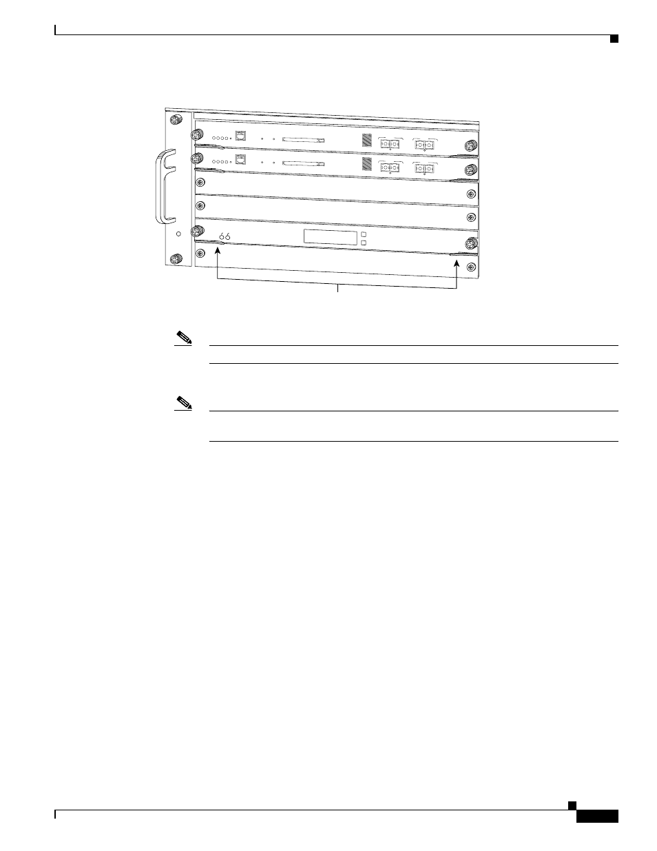
Figure 4
Ejector Lever Closure in a Horizontal Slot Chassis
Note
Failure to fully seat the module in the backplane connector can result in error messages.
e.
Tighten the two captive installation screws on the supervisor engine or module.
Note
Make sure that the ejector levers are fully closed before tightening the captive installation
screws.
Vertical slots
a.
Position the supervisor engine or switching module in the slot. (See
align the sides of the switching-module carrier with the slot guides on the top and bottom of the slot.
1
2
3
FAN
STATUS
4
5
6
SUPERVISOR2
WS-X6K-SUP2-2GE
STATUS SYSTEMCONSOLEPW
R MGMT
RESET
CONSOLE
CONSOLE
PORT
MODE
PCMCIA
EJECT
PORT 1
PORT 2
Switch Load
100%
1%
LINK
LINK
SUPERVISOR2
WS-X6K-SUP2-2GE
ST
AT
U
S
SY
ST
EM
C
O
N
SO
LE
PW
R
M
G
M
T
R
ES
ET
CONSOLE
CONSOLE
PORT
MODE
PCMCIA
EJECT
PORT 1
PORT 2
Switch Load
100%
1%
LINK
LINK
SWITCH FABRIC MDL
WS-C6500-SFM
ST
AT
US
AC
TIV
E
SE
LE
CT
NE
XT
58571
Ejector levers flush
with module faceplate