Dynon Avionics RV-10 Pitch Legacy User Manual
Page 7
DYNON AVIONICS
Servo Mounting Instructions – RV-10 Pitch Kit
6
101046-006 Rev F
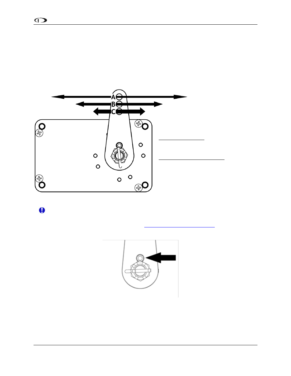
Linkage mount position force and travel
The diagram below illustrates the maximum travel and force available at each linkage mounting
point. As can be seen, the closer you mount the linkage to the shaft, the more force the servo can
deliver. However, this also means the travel of the arm is shorter. Again, ensure that the servo arm is
nowhere near going over-center throughout the entire range of the control system.
Position A should be used in most RV-6 roll installations. Modify mount position with caution and
take all precautions to ensure that a near over center condition cannot occur.
The autopilot safety shear screw should NEVER be removed or adjusted during this
operation. If the shear screw has broken and needs replacement, there is specific
documentation available for this purpose a
Mounting Drawings
The following pages provide detailed views of the mounting and assembly of the servo and
this kit.
Long Arm
Max Linear Travel
A: 3.4”, B: 3.0”, C: 2.6”
Max Force @ 100% Torque
SV32L - A: 18lb, B: 20lb, C: 24lb