Dynon Avionics RV-10 Pitch Legacy User Manual
Page 3
DYNON AVIONICS
Servo Mounting Instructions – RV-10 Pitch Kit
2
101046-006 Rev F
SERVO MOUNTING INSTRUCTIONS – RV-10 PITCH KIT
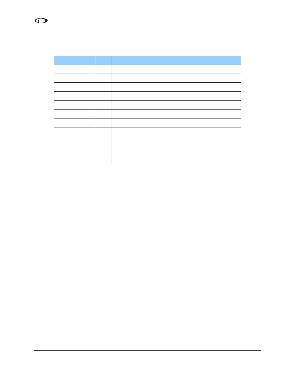
Kit Contents
Dynon Part # QTY Part Description
100836-000
2
Large Male Rod End
100966-008
1
Aluminum Pushrod Tube – 3.0”
100973-000
1
RV10 Pitch Bracket
100975-002
2
AN315-4R Jam Nut
100976-011
2
AN365-1032A Nylon Insert Locknut
100977-000
2
AN970-3 Large Flat Washer
100978-003
10 AN960-10 Small Flat Washer
100979-002
4
MS35333-39 #10 Internal Star Washer
100981-000
4
AN3H-3A Bolt - 3/8"
100981-005
1
AN3H-10A Bolt - 1"
100981-006
1
AN3H-11A Bolt – 1 1/8"
The RV-10 pitch servo mounting kit includes a mounting bracket, pushrod linkage, and most of the
required fasteners to mount the servo and properly link it to the aircraft control system. All Dynon-
supplied parts are illustrated in dark grey to distinguish them from existing aircraft hardware. Refer
to the drawing to locate the servo mounting bracket in the aircraft.
Fasteners along the mounting plate surface must be removed and can be re-used to secure the
bracket in place. The Dynon mounting bracket must be drilled to match the existing hole pattern of
the aircraft plate. Once the bracket has been drilled, fasten it to the aircraft. It is up to the installer
to verify the hardware used is tightened back to aircraft specification.
With the bracket installed in the aircraft, the bell crank must be drilled. Refer to the drawing for
dimensions, and use a supplied AN960-10 washer as a support between the two halves of the bell
crank to avoid crushing when the linkage is fastened.
Install the 4 AN3H-3A bolts, MS35333-39 star washers, and AN960-10 flat washers to secure the
servo to the bracket per the drawing, noting the orientation of the servo output arm. All AN bolts
supplied by Dynon have drilled heads for use with safety wire. With the servo and bell crank
additions in place, torque all fasteners back to original installation specifications and add safety wire
where needed.
With the servo installed, the linkage needs to be assembled. Refer to the illustration and follow
proper rod end installation techniques. Thread both large rod ends with jam nuts into the supplied
3.0" tube. Mounting of the linkage to the servo arm will include the AN3H-10A bolt, AN970-3 large
diameter flat washer (for capturing the rod end bearing), 2 AN960-10 flat washers, and the AN365-
1032A lock nut. The other end of the linkage will require the same type of stack-up, using the longer
AN3H-11A bolt and capturing the washer sandwiched between the halves of the bell crank.
To prevent the possibility of the servo arm going over-center, the servo arm must not travel more
than a total of +/-60º from neutral throughout the control system's range of travel. The linkage