7 push-pull model, 8 maintenance and handling, Push-pull model maintenance and handling – Dillon X Force Gauge User Manual
Page 15
Model X Mechanical Force Gauge User Instructions
15
2.7 Push-Pull model
Do not attempt to weld, cotter pin, or otherwise make tensile connectors a solid part of
the bar since every requirement is different as to the length of the shank that has to be
used.
Dillon will not be liable for any incident that might result from accidental or
intentional screw-out or break-away of the ball-socket connectors. For your own
protection, keep these parts properly seated at all time.
Tare settings cannot be made on the Force Gauge without a slightly resultant loss in
accuracy. This is due to the fact that the dial layout is not 100% linear. Each unit is
individually machined and thus must be individually calibrated. While this makes for
split-hair accuracy, division marks are not equidistant and hence do not lend
themselves to tare adjustment. Instead, any tare weight encountered in a typical test
should simply be deducted.
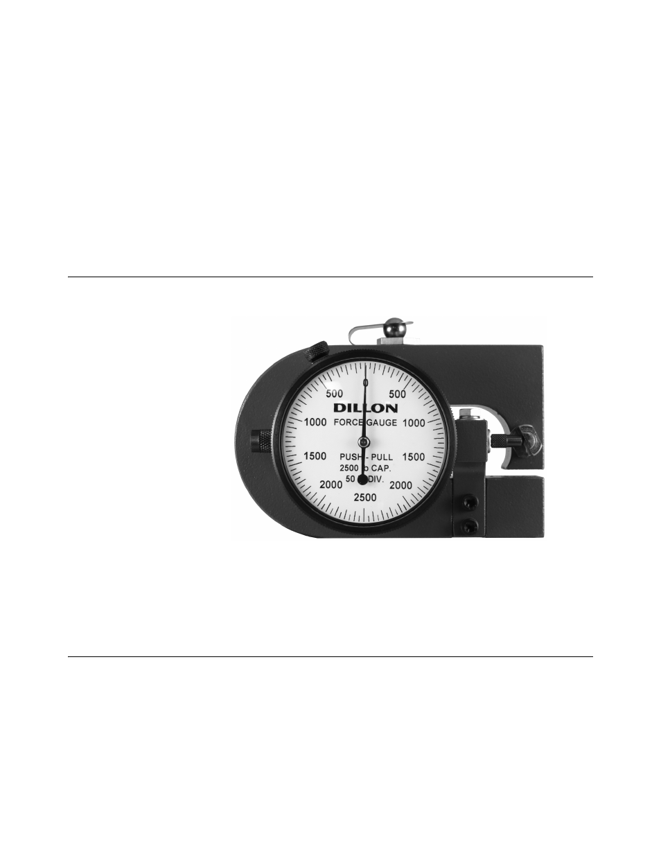
2.7 Push-Pull model
There is one more type of force gauge, a push-pull model, shown in
Figure 2.4 Push-pull model force gauge
This model can be used for both tension and compression situations. As you can see
the dial can go in two directions.
2.8 Maintenance and handling
The Dillon force gauge is a precision instrument and will provide many years of
dependable service if given reasonable care and suitable protection. Many firms make
it a regular practice to return force gauges to their distributors at 6 to 8 month intervals
(depending upon how much they are used) to have accuracy recertified. We
recommend this at least once a year. Consult with your Dillon distributor concerning
any questions you may have about recalibration intervals. Your area may require
periodic proof testing. Consult your local regulations.
Transport and store the force gauge in the supplied storage case when not in use.