Page 3 – Beckett 7600 Quick Start User Manual
Page 3
Page 3
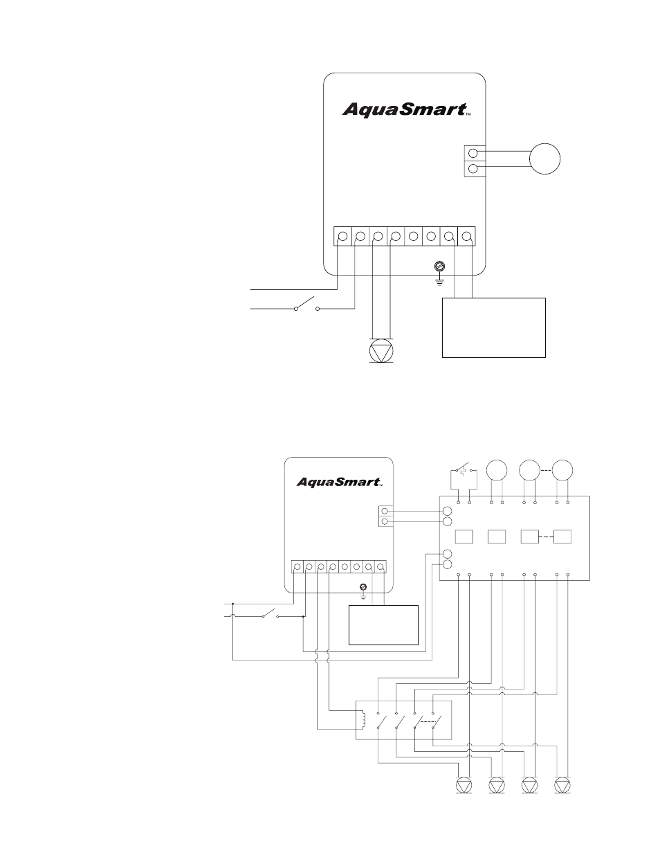
Figure 2 - 7600A/B single-zone connections with or without a tankless coil
Control Wiring:
1. Set “DHWP OFF” (default, see programming
section of the Owner’s Manual for further
instructions)
2. Set “C1 on TT” (default, see programming
section of the Owner’s Manual for further
instructions)
LOW VOLTAGE
THERMOSTAT
L2 L1 C1 C2 ZC ZR B1 B2
P1
CIRCULATOR
120 VAC
120 VAC
NEUTRAL WHITE
HOT SERVICE
SWITCH
BLACK
7600A:
120 VAC BURNER OR
GAS IGNITION SYSTEM
7600B:
24 VAC GAS
IGNITION SYSTEM
TW
TR
WHITE
RED
BLAC
K
WHIT
E
SK10019
Figure 3 - 7600A/B multi-zone connections with Indirect Domestic Hot Water (DHW)
Control Wiring Option: Utilizing a Zone Panel
1. Set “DHWP OFF” (default, see
programming section of the Owner’s
Manual for further instructions) DHW Zone
priority will be determinedby the zone
panel.
2. Set “C1 on TT” (default, see programming
section of the Owner’s Manual for further
instructions)
3. Circulator-on delay will affect all zones.
Circulator-off delay will have no effect. If Circulator-
on delay is not desired, remove the n-pole contactor
and wire the circulators directly to the zone panel.
L2 L1 C1 C2 ZC ZR B1 B2
TR
TW
SK10036
ZONE
PANEL
SERVICE
SWITCH
NEUTRAL
HOT
120 VAC
BLACK
WHITE
X
X
L1
L2
Z1
Z2
Z3
Zn
CIRCULATOR
120 VAC
P1
P2
CIRCULATOR
120 VAC
P3
CIRCULATOR
120 VAC
Pn
CIRCULATOR
120 VAC
n-POLE
CONTACTOR
120 VAC COIL
DHW
AQUASTAT
ZONE 1
LOW
VOLTAGE
THERMOSTAT
ZONE 2
LOW
VOLTAGE
THERMOSTAT
ZONE n
LOW
VOLTAGE
THERMOSTAT
END
SWITCH
7600A:
120 VAC BURNER OR
GAS IGNITION SYSTEM
7600B:
24 VAC GAS
IGNITION SYSTEM