Vernier Dynamics System User Manual
Page 4
7
MASS and DFS
Attach the DFS first, since the plastic screw on the DFS becomes inaccessible when
the MASS is attached.
The DFS must be attached at the opposite end of the cart from the slot flares if you
want to be able to remove the mass without removing the DFS.
MASS and LGA
For this combination, the order of attachment is not critical:
MASS, DFS, and LGA
This is a similar case to the MASS and DFS, where the DFS must be attached first.
There is sufficient room on the new MASS bolt to piggyback the LGA on top of the
mass before attaching the small barrel.
8
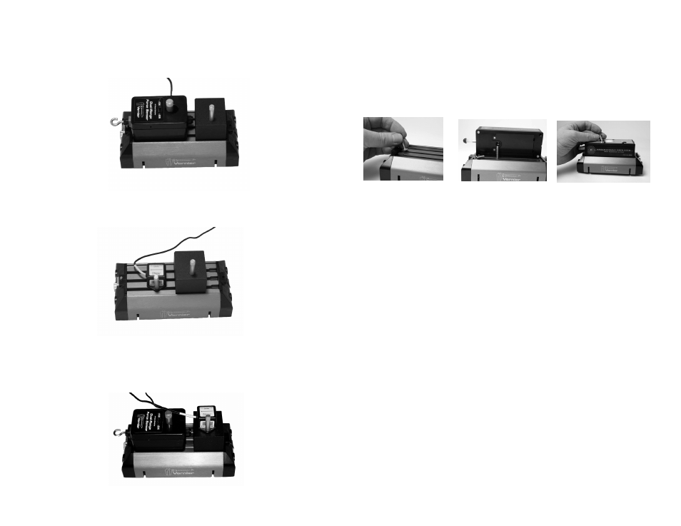
Wireless Dynamics Sensor System
Mounting on a Vernier Dynamics Cart
For connection to a Vernier Dynamics cart use a 5/8" × 10-24 binding barrel and a
hex-head bolt (1" × 10-24). First place the bolt head in the middle slot of the top of
the Vernier dynamics cart. Then lower the WDSS on top of the cart and insert the
binding barrel in the large hole of the WDSS. The bolt threads into the binding
barrel. Tighten the binding barrel. The process is shown in the series of photos
below:
Hints for Using VDS
Don’t install the magnets unless you know you want to use them. They will
interfere if you perform an experiment with a force sensor riding on the cart, since
the force sensor will then not read the total force acting on the cart.
The magnets can be hard to pull apart if they stick together before installation;
slide them across one another to separate.
The conventional arrangement for magnets to have the cart ends attract the S end
of a compass needle. The key thing is that all magnets repel, so if you use the
opposite convention everywhere, no harm is done.
The magnets are designed for fairly gentle collisions. If the cart is moving too
quickly, the magnetic forces may cause the cart to jump off the track to the side.
If this happens, use a lower initial velocity for the cart.
Keep the track clean; if it is very dusty the carts will not roll smoothly.
Use lower speeds and lower inclines than you might initially choose; the physics
is the same and students will have more time to observe what is happening.
Attach the track feet, sliding at least one in about 30 cm before inserting the
Motion Detector bracket.
Study the Motion Detector bracket photo carefully and note that the bracket is
attached to the underside of the track. A common error is to attach the bracket to
the top slot on the track.
Some Dual Range Force Sensors come with a plastic bolt that is too long to allow
simultaneous attachment of the DFS with a MASS. If your bolt is long, use a wire
cutter to remove a few threads at a time.