Vernier Dynamics System User Manual
Page 2
3
Both the plunger and simple carts have a mass of 500 g. Adding accessories will
change the mass.
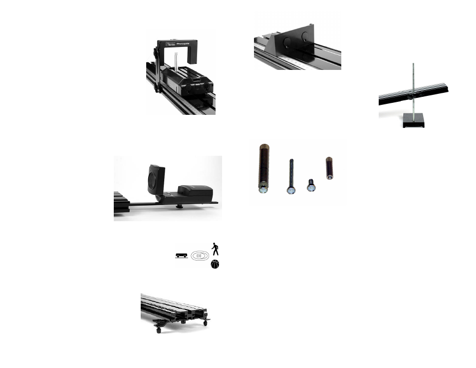
Photogate Bracket
Photogate brackets are attached to the side of the
track. With the nut loosely on the T-handled bolt,
slide the nut into the side channel of the track.
Attach the photogate using the supplied wing bolt
in the long slot. Adjust the gate height so the beam
intercepts the desired portion of the target.
Motion Detector Bracket
Any Vernier Motion Detector with a hinged head can be attached to the supplied
Motion Detector Bracket. The Motion Detector Bracket has a pin to locate the
Motion Detector on the bracket. There is a knob, nut and bolt to attach the bracket to
the track underside, and a threaded hole at the end near the pin. To assemble, place
the Motion Detector with the back
end over the pin of the bracket. Insert
the screw through the slot into the
threaded insert on the detector with
the hinge toward the track, and
tighten. Insert the bracket into the slot
in the underside of the track as shown
in the photo. When the Motion
Detector is not attached to the
bracket, its mounting screw can be
stored in the threaded hole near the
pin.
Newer Vernier Motion Detectors (green or black case with
adjustable sensitivity) can be placed so that the sensor is 15 cm
from the end of the track. The carts can then be detected
properly all the way to the end. The track mode is appropriate
for the dynamics system.
Double Foot Stand
The double foot stand slides into the end of the
track, with the nut in the center slot of the track
underside. Adjust the height as desired. Install
the stands before attaching the motion detector
bracket.
4
Adjustable End Stop
The adjustable end stop slides into the end of
the track. Adjust the position as desired. Insert
magnets in the end stop if desired.
Rod Clamp
The rod clamp is used to support the track with a
user-supplied ring stand. Insert the rod clamp nut
into the side of the track. Adjust the height as
desired.
Mounting Hardware
The supplied mounting hardware is used to
attach devices to the cart, such as a force
sensor, accelerometer, or mass. To attach a
Wireless Dynamics Sensor System (WDSS)
use the hardware supplied with that device.
The hex-head bolts may be attached to any
point along the slots in the cart, but the head
must be inserted in the flare region of the
slots. Tighten the threaded barrels on the
bolts.