Step 7 – Calphalon ESSENTIALS 8353 User Manual
Page 12
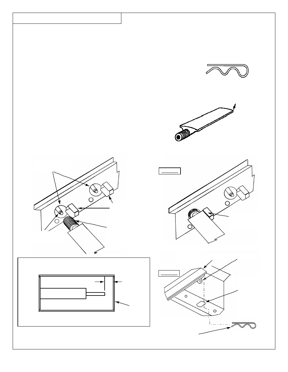
FIG. 6B
Burner
Locator
Hole in
lower
shoulder
of rear
firewall
Burner Peg
FIG. 6A
Item 27
COTTER PIN
Item 34
BURNER
Holes in Front
Firewall
Gas Nozzle
Control Valve
Gas Collector
Plate and
Electrode
Venturi end of
Burner inserted
over Gas Control
Valve Nozzle
Top Plate of
Gas Collector
Plate
REFERENCE: ELECTRODE GAP
Adjust Tab if greater than 3/16”.
ELECTRODE
3/16”
GAP
MAX.
TAB-GAS
COLLECTOR
PLATE
STEP 7
- INSTALL BURNERS
•Repeat above steps for remaining burners.
•Remove plastic covering from Burners(3)
and remove Cotter Pins(3) from Burner Peg.
•Fit venturi end of Burner through hole in the inside firewall of
Body (behind Control Panel) and onto Gas Control Valve
Nozzle (FIG. 6A.) Be careful not to bend or force Gas
Collector Plates.
•Place other end of Burner on lower shoulder of rear
firewall so Burner Peg rests in Burner Locator Hole
as shown ( FIG. 6B.)
•Using pliers, from underside of grill Body,
insert Cotter Pin through hole in Burner
Peg to secure.
12
BURNER PEG
Cotter Pin - Install
from underneath
Backside of grill
Burner