Pilz PIT en1.0 holder User Manual
Page 2
- 2 -
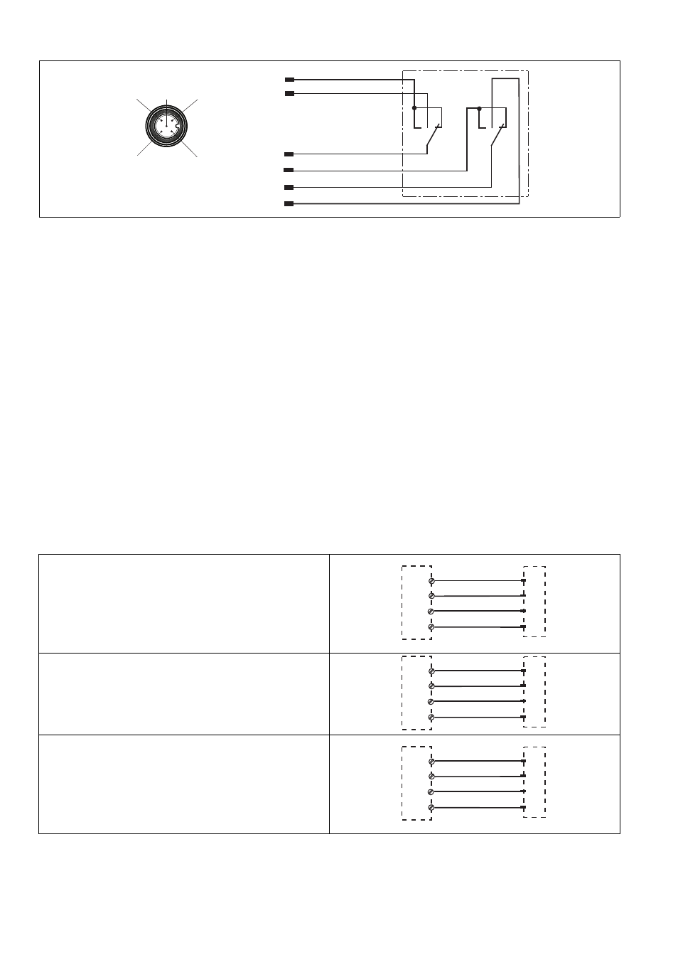
Blockschaltbild/Klemmenbelegung
Block diagram/terminal configuration
Schéma de principe / affectation des
bornes
Funktionsbeschreibung
1221887115
Der Zustimmtaster ist 3-stufig ausgeführt:
nicht gedrückt: kein Zustimmsignal (Aus)
gedrückt bis Mittelstellung: Zustimmsignal
aktiviert (Ein, Zustimmfunktion)
gedrückt bis Endanschlag: kein Zustimmsi-
gnal (Aus, Panikfunktion)
Dadurch ist gewährleistet, dass sowohl bei
Loslassen als auch bei Durchdrücken des Ta-
sters das Zustimmsignal unterbrochen wird.
Wird der Zustimmtaster bis Endanschlag ge-
drückt und dann wieder losgelassen, bleibt er
auch während des Wechsels ausgeschaltet.
Function description
The switch is a 3-stage enabling switch:
Not operated: no enabling signal (off)
Operated as far as middle setting: enabling
signal activated (on, enabling function)
Operated as far as end stop: no enabling sig-
nal (off, panic function)
This guarantees that the enabling signal is in-
terrupted not only when the switch is released
but also when it is fully operated.
If the enabling switch is fully operated as far as
the end stop and then released, it will remain
switched off during the changeover.
Description du fonctionnement
La poignée d'assentiment possède 3 positions
:
non appuyée : pas de signal d'assentiment
(éteint)
appuyée jusqu'en position centrale : signal
d'assentiment activé (allumé, fonction de va-
lidation)
appuyée jusqu'à la butée finale : pas de si-
gnal d'assentiment (éteint, fonction de pani-
que)
Cela garantit que le signal d'assentiment est in-
terrompu à la fois en cas de relâchement et en
cas d'appui continu sur la poignée.
Si la poignée d'assentiment est appuyée jus-
qu'à la butée finale puis relâchée, elle reste à
l'arrêt même durant le changement.
Verdrahtung
1221897611
Beachten Sie beim Verdrahten:
Schützen Sie die Leitungen vor Beschädi-
gung z. B. durch einen Schutzschlauch.
Verwenden Sie geschirmte Leitungen und
verbinden Sie den Schirm mit dem Schutzlei-
tersystem der Maschine/Anlage.
Wiring
When wiring, please note:
Protect the cables from damage, by using a
protective tube for example.
Use shielded cables and connect the shield
to the plant/machine's protective earth sys-
tem.
Câblage
Lors du câblage, tenez compte des éléments
suivants :
Protégez les câbles contre les dommages,
par exemple, à l'aide d'un tube de protec-
tion.
Utilisez des câbles blindés et reliez le blinda-
ge au conducteur de protection (PE) de la
machine / installation.
Anschluss an Auswertegerät
Connection to evaluation device
Raccordement à l'unité de contrôle
Anschluss an PNOZ X, PNOZsigma und
PNOZelog
Connection to PNOZ X, PNOZsigma,
PNOZelog
Raccordement aux PNOZ X, PNOZsigma,
PNOZelog
Anschluss an PDP67 F 8DI ION
1485886731
Der Anschluss erfolgt über den Adapter
PSEN mag ad (s. Bedienungsanleitung PSEN
adapt PSS67/PDP67 4p).
Connection to PDP67 F 8DI ION
The connection is made via the adapter
PSEN mag ad (see operating manual PSEN
adapt PSS67/PDP67 4p).
Raccordement au PDP67 F 8DI ION
Le raccordement a lieu par l'adaptateur
PSEN mag ad (voir le manuel d'utilisation PSEN
adapt PSS67/PDP67 4p).
1
2
3
4
5
grün/green/vert
weiß/white/blanc
gelb/yellow/jaune
braun/brown/marron
grau/grey/gris
2
3
4
1
5
rosa/pink/rose
n. c.
PNOZ e1p
PNOZ e1.1p
PNOZ e1vp
PNOZ e6.1p
PNOZ e6vp
PNOZ s3
PNOZ s4
PNOZ s5
PNOZ X2C
PNOZ X2
PNOZ X2.7P
PNOZ X2.8P
PNOZ X2.9P
S11
S12
S21
S22
weiß/white/blanc
gelb/yellow/jaune
grün/green/vert
braun/brown/marron
3
4
1
2
PNOZ e5.11p
A1
S32
A1
S24
weiß/white/blanc
gelb/yellow/jaune
grün/green/vert
braun/brown/marron
3
4
1
2
PNOZ X3.1
PNOZ X3P
PNOZ X3
PNOZ X3.10P
PNOZ XV2
PNOZ XV2P
PNOZ XV3
PNOZ XV3P
S31
S32
S21
S22
weiß/white/blanc
gelb/yellow/jaune
grün/green/vert
braun/brown/marron
3
4
1
2