Step – Petsafe Deluxe In-Ground Cat Fence™ User Manual
Page 10
10
1-800-732-2677
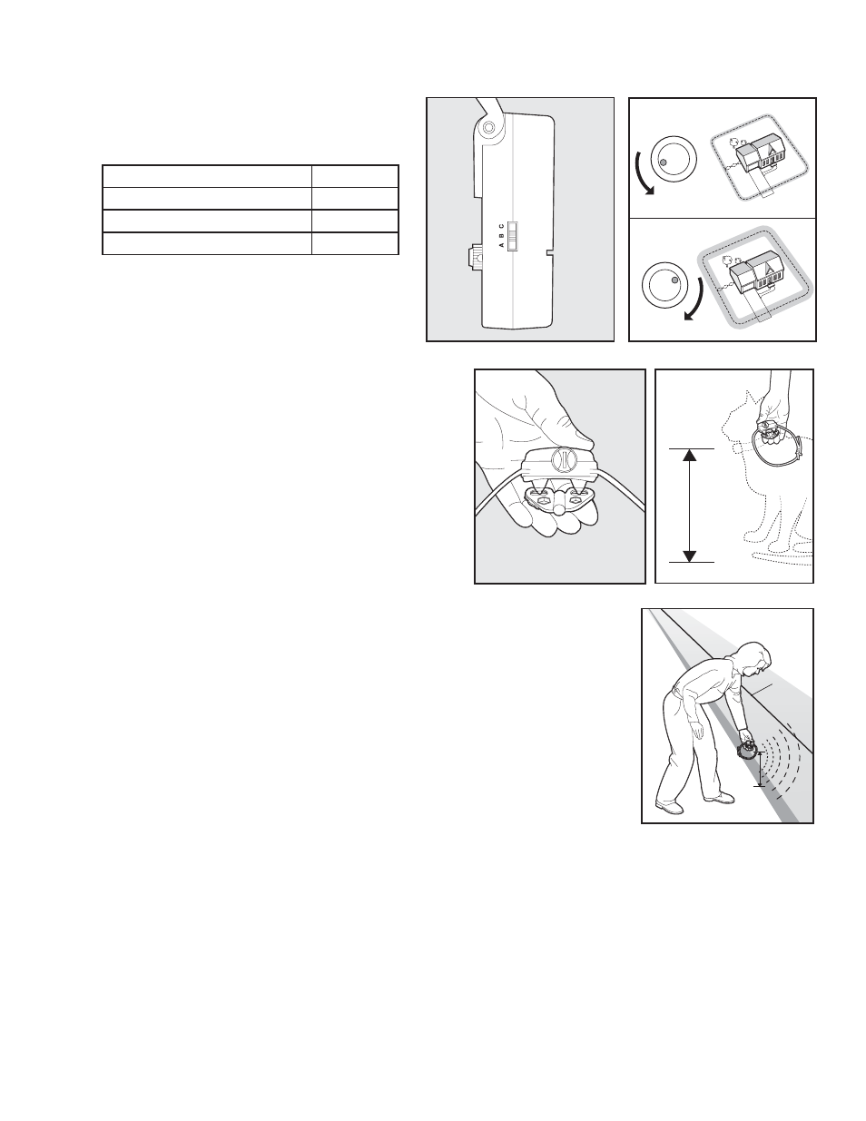
Set the Boundary Width and Test the Receiver Collar
The Boundary Control Switch on the side of the
Fence Transmitter has three settings (6A). Setting B
is used for most properties. The following table will
indicate the setting you should use.
Amount of Wire
Setting
Up to 1300 feet
B
1300-2400 feet
C
Greater than 2400 feet
A
Use the Boundary Width Control knob to set the
width of the Warning Zone and Static Correction
Zone (6B). Set the Boundary Width as wide as
possible to give your cat the widest Warning and
Static Correction Zones without reducing the
6A
5
2
8
4
10
3
9
1
7
0
6
5
2
8
4
10
3
9
1
7
0
6
6B
Pet Area too much.
Note: The Boundary Width Control knob does not change the
Static Correction Level.
To identify the Warning and Static Correction Zones,
make sure the Receiver Collar batteries are properly
installed, the Static Correction Level is set at 2 or above,
and the Test Light Contacts are held to the Contact
Points (6C). Walk toward the Boundary Wire, holding
the Receiver Collar at your cat’s neck level (6D) until the
Receiver Collar beeps (6E).
Note: The Receiver Collar is waterproof, which can make the
beep hard to hear.
If the Receiver Collar does not beep at the desired range,
adjust the Boundary Width Control knob to the desired
6C
6D
setting. Turning the Boundary Width Control knob clockwise increases the Boundary
Width while turning it counterclockwise decreases it (6B). Repeat this activity as needed
until the Receiver Collar beeps at the desired distance from the Boundary Wire.
The numbers on the Boundary Width Control knob indicate signal strength and are not
representative of Boundary Width footage. If adjusting the Boundary Width Control knob
does not give the desired range, adjust the Boundary Control Switch to another setting
to achieve your desired range. If using a Double Loop, you may need to increase the
separation of the Boundary Wire to achieve desired range.
The Receiver Collar beeps as a warning tone and ticks when delivering a Static Correction.
After hearing the beep, continue to walk towards the wire. The Receiver Collar should tick
and the Test Light should fl ash, indicating the Static Correction as you enter the Static
Correction Zone (6E). A warning tone and the fl ashing of the Test Light indicate that the
Receiver Collar and the system are working properly and that you are ready to start burying
the Boundary Wire. If the Receiver Collar did not beep or the Test Light did not fl ash, see
the “Troubleshooting” section.
Boundary
Wire
6E
Note: The Boundary Width is broken down into 20% Warning Zone and 80% Static Correction Zone.
Step
6