Fig 3 fig 4 – PDR Mounts pstm4060 User Manual
Page 6
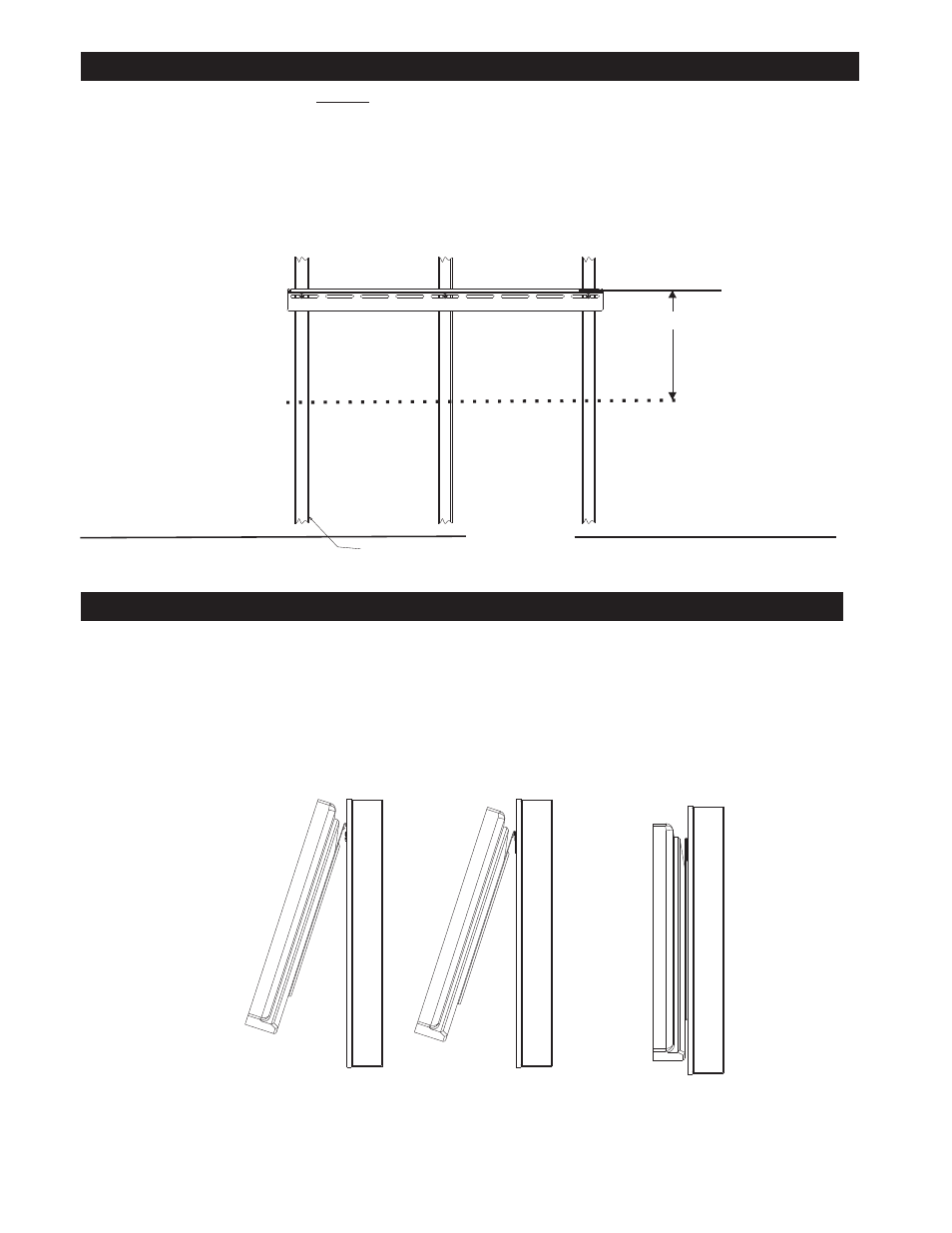
WOOD STUDS
MOUNTING DISPLAY ON THE WALL BRACKET
XXXX
Fig 3
Fig 4
FLOOR LINE
VIEWING
HORIZONTAL
CENTER LINE
1: The bracket must be secured to the centered on 2 or 3 wall studs capable of holding at least four times the weight of the unit.
2: Use a stud finder to determine the stud center line of the wall stud.
3: Use the sketch from FIG 2 to determine the height of the wall mount bracket (B).
4: Pre drill 1/8” (3mm) holes for the lag bolts Fig 3.
5: With the flange facing up on the wall bracket, use the 3 lag bolts ©
level and secure the mounting plate to the center of the wall studs. See Fig 3
FASTEN MOUNTING PLATE TO WALL
Add offset from FIG 2
1: Place the display with bracket (A) attached onto the wall bracket (B) SEE FIG 4
2: The Display bottom needs to be puled away from the wall about 20 degrees, and lowered onto the wall bracket
and allowed to rest on the wall.
3: The mount cannot be removed or accidently dislodged from the wall unless the bottom is pulled away 20
degrees and lifted up.
6
STANDARD 2 X 4 CONSTRUCTION
16” OR 24” SPACING
Caution DO NOT OVER TIGHTEN LAG BOLTS