Fig 5 fig 6, Fig 7 – PDR Mounts pdm110thn User Manual
Page 4
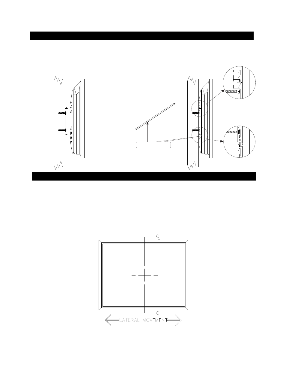
3. MOUNT THE DISPLAY TO THE WALL MOUNT BRACKET
Fig 5
Fig 6
4. Adjust lateral movement
Lateral Movement:
4
Fig 7
Once the
display on the wall is complete you can still move the display left to right to optimize the final viewing position, by gently sliding the unit on the wall
bracket. The adjustment distance will vary depending on the display model being installed.
Fig 7
installation of the
Locking bar
Lift the display with the brackets
A attached, onto the wall plate. See Fig 5
Position the hooks on bracket
A to the wall plate B, using the desired height adjustment slot. See Fig 5 & 6
Insert the locking bar (C) as shown in
Fig 5 (B) .
Make sure the display brackets engage the rails on the wall mount bracket (B) See Fig 6.
Slide the locking bar thru the bracket (A) slots. If security is desired place a lock (not supplied) thru the hole in the locking bar.
Fig 6
1/2”
1
1/2”
1
Height adjustment slots
Locking bar in place