Fig 4 fig 5 fig 6 – PDR Mounts awm125-120 User Manual
Page 6
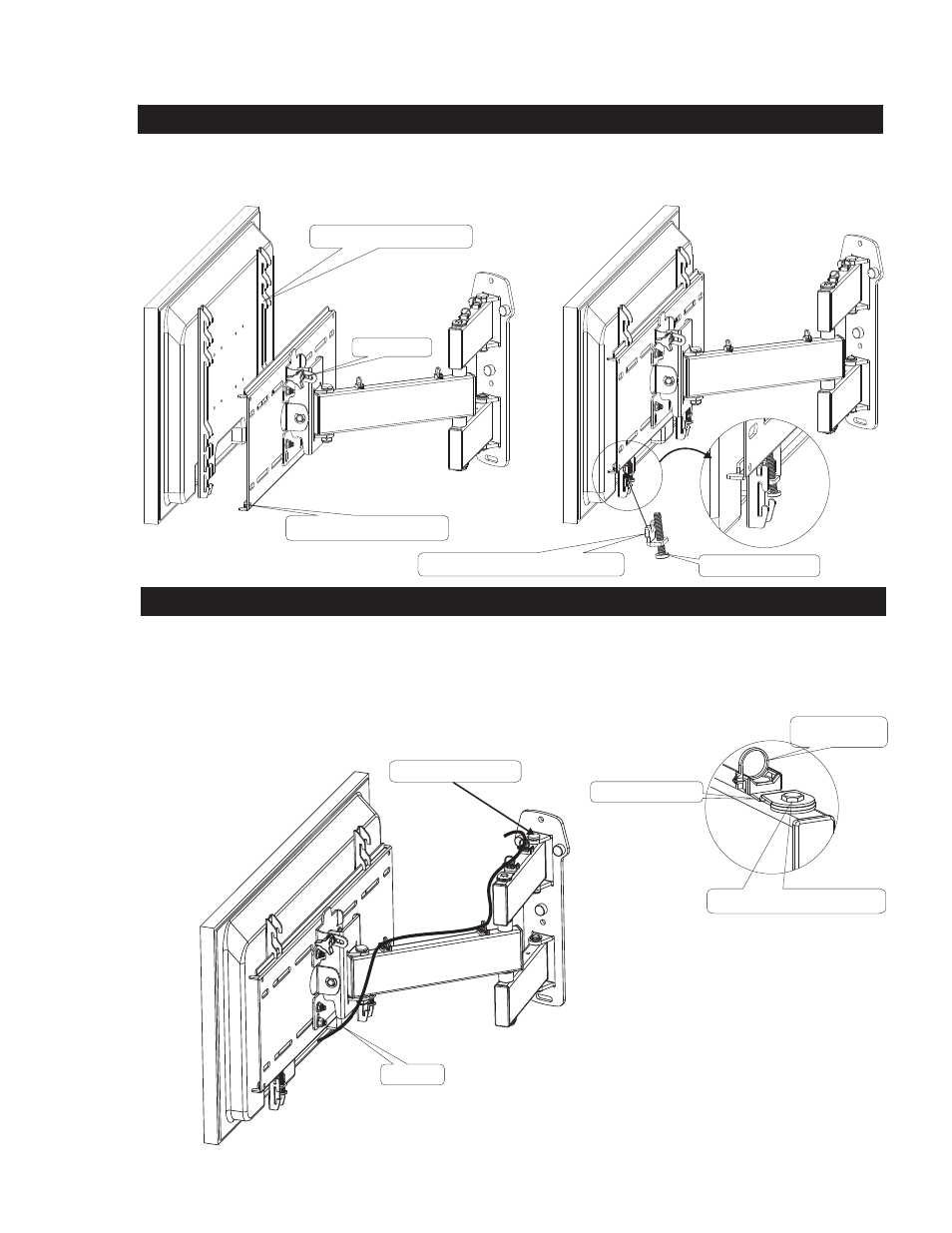
3. Mounting the display onto the AWM125-120 Articulating arm
3. Final adjustment and cable management
SCREW LOCK TAB
NYLON ZIP TIE
6
Fig 4
Fig 5
Fig 6
1: With the display brackets attached to the display, lift and place the brackets on to the
in either the top middle or bottom slots.
SEE FIG 4
2: Center the display from left to right on the mounting plate.
3: Screw the 1/4-20 screw (10) into the locking plate (13)
4: Place the locking tab assembly into the slots on the display bracket, and tighten the 1/4-20 screw (10) on each locking tab assembly.
SEE FIG 5
mounting plate
Adjust by tightening the tension bolts to suit the desired freedom of movement
See fig 6
1: Lift the tie holder(16) on the lock tab to allow access the bolt to adjust the tension on the arm center. Replace the tie holder (16) after adjustment.
3: Two other tension bolts can be tightened or loosened to suit.
SEE FIG 6
2: Adjust the tilt by loosening the Tri knob on the side of the
AWM125-120 and adjust back or forward for best viewing angle. See fig 6
3: Place the plastic tie holders (16) in the desired holes, and using zip ties (14) attach the cables.
4: Make sure you articulate the mount from side to side looking for any pinching of the cables.
MOUNTING PLATE
DISPLAY BRACKETS
LOCKING TAB ASSEMBLY
1/4-20 screw
large view
TENSION BOLTS
CABLE
TENSION ADJUSTMENT BOLT
TRI KNOB