Fig 4 fig 5 fig 6 – PDR Mounts awm125 with pdm110thn User Manual
Page 6
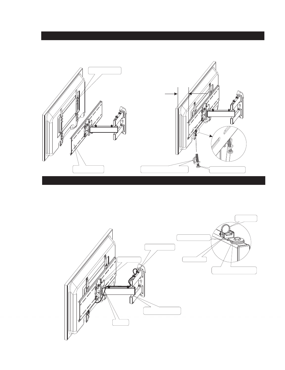
3. Mounting the display onto the AWM125-110 Articulating arm
3. Final adjustment and cable management
Screw lock tab
Nylon zip tie
6
Fig 4
Fig 5
Fig 6
1: With the display brackets attached to the display, lift and place the brackets on to the
.
SEE FIG 4
2: Center the display from left to right on the mounting plate.
SEE FIG 5
3: Screw the 1/4-20 screw (10) into the locking plate (13)
4: Place the locking tab assembly into the slots on the display bracket, and tighten the 1/4-20 screw (10) on each locking plate assembly.
SEE FIG 5
mounting plate
Adjust by tightening the tension bolts to suit the desired freedom of movement
See fig 6
1: Remove the tie holder,
(16 and screw # 17) and screw lock tab to allow access to the center pivot joint bolt. To adjust the
tension on the arm center, tighten the bolt to suite . Replace the tie holder and screw(
) and the screw lock tab after adjustment.
3: Two other tension bolts can be tightened or loosened to suit.
See fig 6
2: Adjust the tilt by loosening the Tri knob on the side of the
AWM125-110 and adjust up or down for best viewing angle. See fig 6 & page 4
3:
Place the plastic tie holders and screw(16 and screw 17) in the desired locations, and use zip ties (14) to attach the cables.
4: Make sure you articulate the mount from side to side to avoid pinching the cables.
screw
16 and screw # 17
Mounting plate
Display brackets
Locking plate assembly
1/4-20 screw
large view
Tension bolts
Cable
Tension adjustment bolt
Tri knob
Equal space
Each end
Center pivot joint
Tie holder