Vermont Casting SR30SHK User Manual
Page 4
4
3311956
Tools Required
8” adjustable crescent wrench; pipe thread sealant compound or teflon tape; 12” pipe wrench or chan-
nel lock pliers.
Gas Plumbed on Left Hand Side of Fireplace
NOTE: Your gas log set is assembled at the factory to be installed in a fireplace plumbed with the gas
on the right side (facing). If your fireplace is plumbed with the gas on the left side, you may remove the
u-burner tube from the burner pan by removing the 3/4” knockout at the left back of the burner pan and
reinstalling the u-burner tube 180 degrees from its original position. You may also run a flexible connec-
tor (or as per local codes) along the back wall of the fireplace to bring your gas line to the right hand
side. You can then place the set in front of the flexible connector.
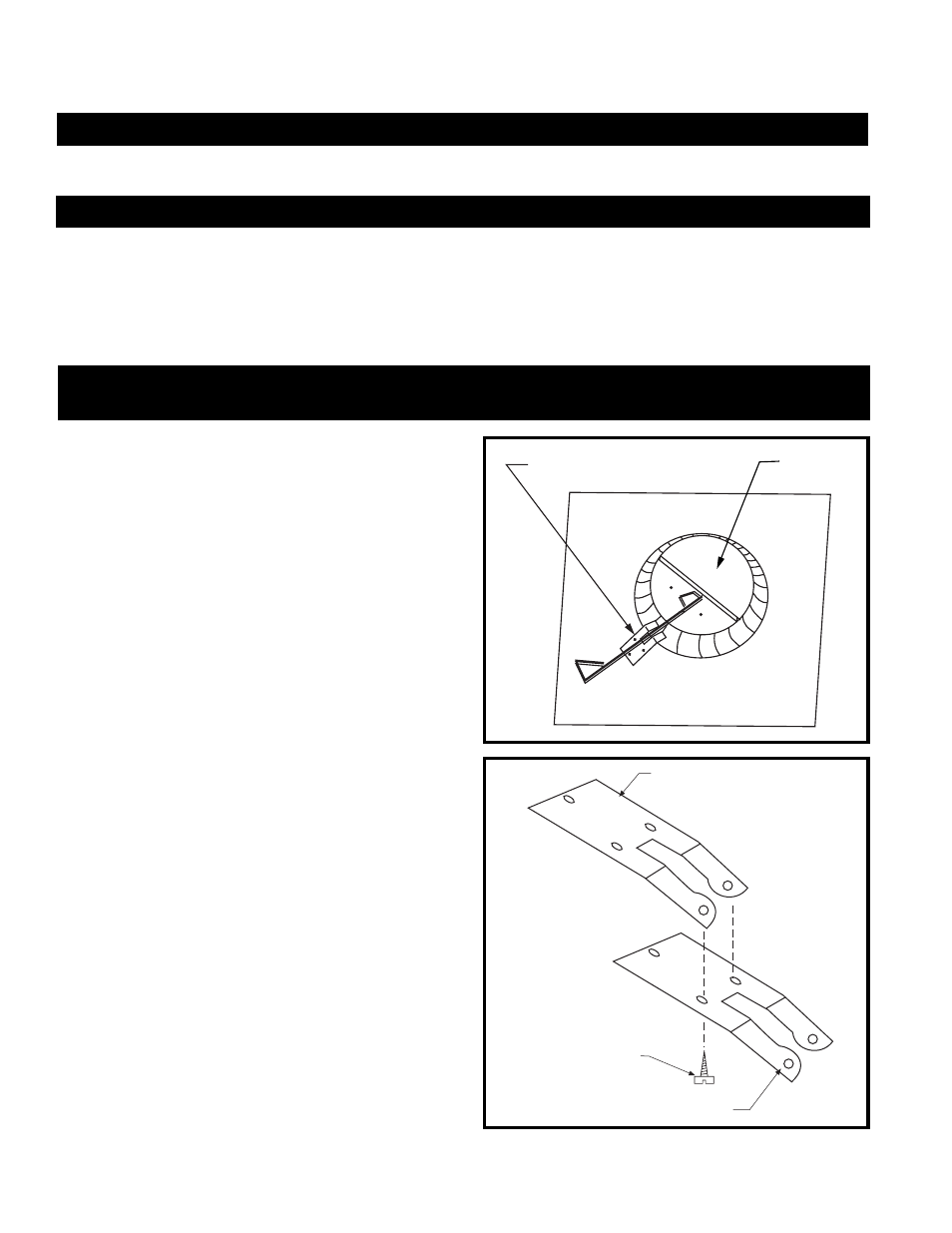
Damper Stop Installation:
For Use with BR, BC, SR, SC, TF and TL Series CFM Specialty Home Products Fireplaces
This Damper Stop is designed to work on all CFM
Specialty Home Products BR, BC, SR, SC, TF and
TL series fireplaces. For all other fireplaces, refer
to Page 6.
When installing a decorative gas appliance in a
fireplace, some local codes require this Damper
Stop to be used so the Damper will not close
completely. To install the Damper Stop:
The Damper Locking Bracket is already installed
on all BR, BC, SR, SC, TF and TL fireplaces.
Locate the Damper Locking Bracket on the left
side of the fireplace’s Combustion Dome. (Fig. 1)
With the Damper open, align the two slots on
either side of the cut-out on the Damper Stop with
the two small holes on the angled portion of the
Damper Locking Bracket. Attach the Damper Stop
with the Screws provided, as shown in Figure 2.
NOTE: Some of the early fireplace units may not
have the holes in the end of the Damper Locking
Bracket. If this is the case, use the Damper Stop
as a template to drill two (2) 1/8” holes in the
Damper Locking Bracket to mount the Damper
Stop.
Damper Locking Bracket
Damper Plate
DP100
Figure 1
Damper Locking
Bracket
Damper Stop Screw
Damper Stop
DP101
Figure 3