M2tech, Front panel – M2TECH hiFace Evo User Manual
Page 5
hi
F
ace
E
vo
192
k
H
z
/24bit digital audio interface
REVISION 1.o – JULY 2010
Copyright © 2010, M2Tech Snc di Manunta & Marino
5
M2Tech
www.m2tech.biz
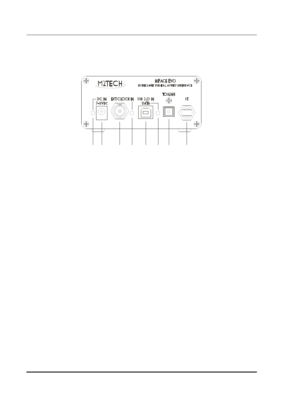
1. Front Panel
1
2
3
4
5
6
7
8
Figure 1
1) Supply input. Apply a voltage in the range 7V to 11V. Tip is positive, ring is negative.
This input is protected against polarity inversion. 2mm tip jack supply connector
2) External clock in. Apply a clock source if you need higher precision and stability than
provided by the internal oscillators. Please remember that a suitable clock (22.5792MHz or
24.576MHz) must be provided depending on the sampling frequency of files to be played
back. Please see the specifications section for absolute maximum ratings. This input is
galvanically isolated by a pulse transformer. 75 Ohm female BNC connector.
3) USB input. Connect to host with a suitable 2.0 USB cable. Female B USB connector
4) Optical Toslink™ output. Connect to DAC or receiver with a Toslink™ optical fiber.
Toslink™ connector.
5) Optical AT&T ST output. Connect to DAC with a 62.5/125um multicore glass optical
fiber. This output is compliant with Avago AV02-0723AN application note. ST connector.
6) Power indicator LED. Turns on in green when power is applied to hiFace Evo.
7) External clock indicator. Turns on in green when an external clock is applied to the
related input.
8) Data indicator. Turns on in green whenever the host is sending data to the hiFace Evo