Assembly instructions, Step 2 step 3, Step 1 – Home Styles 5661-25L User Manual
Page 2
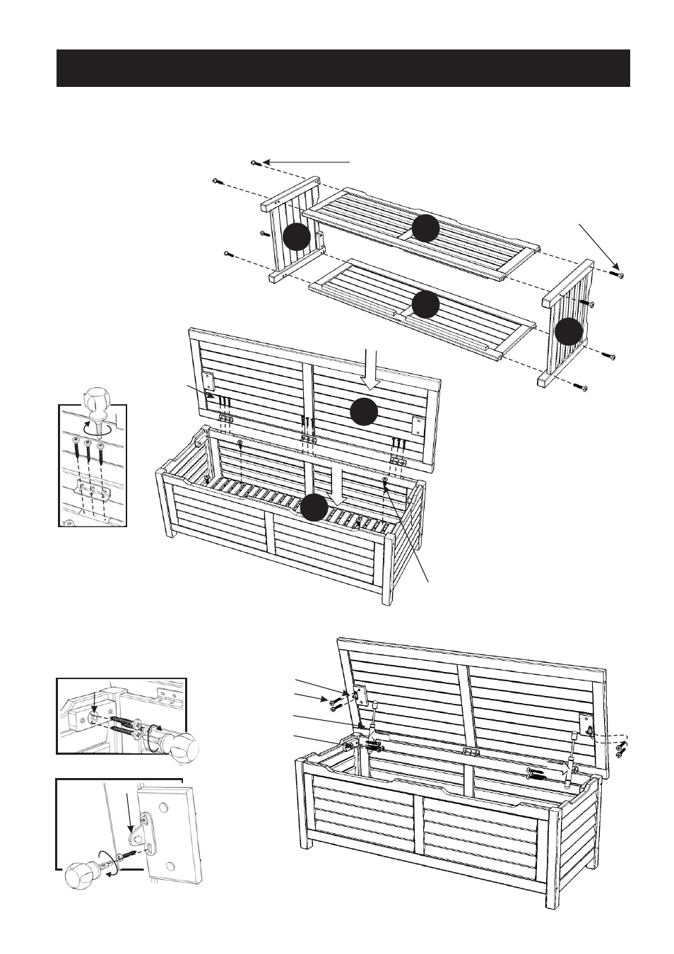
Assembly Instructions
Head Cap Bolt (short)
Wood Screw
Steel Plate B
Steel Plate A
Support
Head Cap Bolt (long)
Head Cap Bolt (long)
Wood Screw
STEP 2
STEP 3
Place Bottom Panel (F) into
unit with Head Cap Bolts(short).
Attach Seat (A) to unit with
Wood Screws. (See figure 1)
Attach Steel Plate A and B to unit with
Wood Screws into the pre-drilled holes.
(See figure 2 and 3)
Attach Supports to Steel Plate A and B.
STEP 1
Attach Front Panel (B) and
Back Panel (C) to Side Panel (D)
with Head Cap Bolts (long).
Attach Side Panel (E) to
unit with Head Cap Bolts (long).
IMPORTANT
* Do not tighten up all the screws until each part is properly assembled.
* You should keep Hex Wrench in a safe place as you may need to tighten up the Head Cap Bolts in the future.
* Use a soft cloth between these parts and the floor.
B
C
D
E
F
A
Figure 1
Figure 2
Figure 3
Steel Plate A
Steel Plate B
- 5050-34 (4 pages)
- 5516-88 (2 pages)
- 5000-89 (3 pages)
- 5518-28 (3 pages)
- 5002-89 (2 pages)
- 5033-88 (2 pages)
- 5003-89 (2 pages)
- 5559-34586 (1 page)
- 5559-34586 (2 pages)
- 5559-3458 (2 pages)
- 5559-3086 (2 pages)
- 5559-3258 (2 pages)
- 5559-3596 (2 pages)
- 5559-83 (4 pages)
- 5660-5985 (2 pages)
- 5660-5985 (3 pages)
- 5660-5984 (2 pages)
- 5660-5984 (3 pages)
- 5660-5983 (2 pages)
- 5660-5983 (3 pages)
- 5660-5982 (2 pages)
- 5660-5982 (3 pages)
- 5660-5981 (2 pages)
- 5660-5981 (3 pages)
- 5660-308 (4 pages)
- 5601-3658 (2 pages)
- 5670-3058 (3 pages)
- 5670-3058 (2 pages)
- 5670-3058 (2 pages)
- 5670-359 (3 pages)
- 5670-359 (2 pages)
- 5800-998 (3 pages)
- 5558-83 (4 pages)
- 5555-8312 (3 pages)
- 5555-36 (2 pages)
- 5554-8312 (3 pages)
- 5552-8312 (3 pages)
- 5660-9982 (3 pages)
- 5660-9982 (4 pages)
- 5555-89 (1 page)
- 5554-325 (2 pages)
- 5554-802 (1 page)
- 5555-328 (2 pages)
- 5554-308 (2 pages)