Cs-8050, Cs-8050 system diagram – Crimestopper Security Products CS-8050 User Manual
Page 8
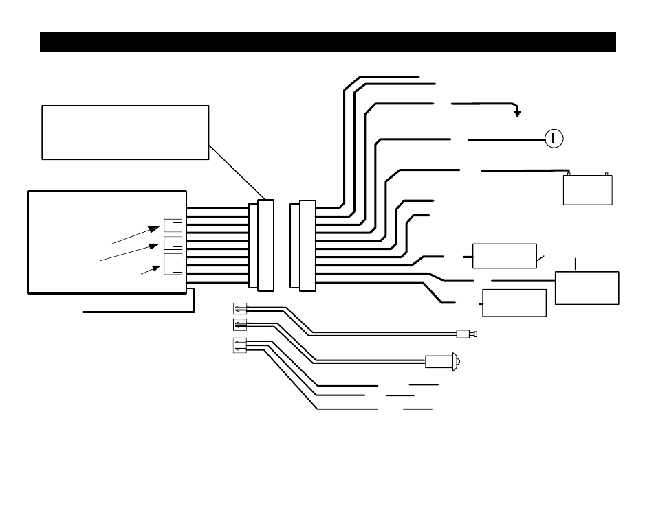
IMMOBILIZER CIRCUIT #1
#1
#2
RED PLUG: LED
BLUE PLUG: VALET
CS-8050
LED
#3
VALET/
PROGRAM
SWITCH
+
BATTERY
(-) NEGATIVE
ARMED OUTPUT
IGNITION
-
#4
#5
#6
+12V
GROUND
#7
(-) NEG. DOME
OR OEM
DISARM
(-) NEGATIVE
HORN OUTPUT
#8
#9
#10
IMMOBILIZER
CIRCUIT #2
(On Board Relay)
(On Board Relay)
WHITE PLUG: DOOR LOCKS
BLUE
RED
WHITE
GREEN
(-) LOCK OUTPUT
BLUE
(-) UNLOCK OUTPUT
RED
+12V FOR RELAYS
MAY REQUIRE RELAY
ANTENNA
*
*
Some systems may not include
a large connector here, however
the wiring diagram is identical.
CS-8050 SYSTEM DIAGRAM
See also other documents in the category Crimestopper Security Products Car alarm:
- EZ-95FM (32 pages)
- CS-865RKE (12 pages)
- RS800 Series II (4 pages)
- CS-2008PC (19 pages)
- EZ-777 TW2 (16 pages)
- EZ-64TW1 (28 pages)
- CS-2011RS IV (30 pages)
- CS-2011RS IV (28 pages)
- SERIES II CS-2004DC II (27 pages)
- CS-2003DC SERIES II (18 pages)
- CS-2004TW1 (24 pages)
- CS-2004DC (20 pages)
- RS901 (13 pages)
- EZ-33DP (16 pages)
- CS-2016FM (21 pages)
- RS1905FM (32 pages)
- CS-2000DP-TW2 (24 pages)
- CS-2001 (12 pages)
- CS-2004DC (24 pages)
- CS-2000 (16 pages)
- CS-883 OEM (12 pages)
- CS-855RKE (12 pages)
- CS-2014TW2 (20 pages)
- RS-1704TW2 (20 pages)
- EZ-84FM (20 pages)
- RS900 (28 pages)
- Series IV Super Rage CS-2011RS (16 pages)
- EZ-10 (12 pages)
- EZ-30 (20 pages)
- CS-2000DPII TW2 (24 pages)
- CS-2205 (32 pages)
- EZ-30DP (29 pages)
- CS-2013FM (26 pages)
- CS-2100 (9 pages)
- CS-2001FC (20 pages)
- CS-2012DP-TW1 (32 pages)
- CS-2012DP-TW1 (32 pages)
- FS-20 (12 pages)
- CS-2011RS (16 pages)
- CS-882 (10 pages)
- TN-4011 (14 pages)
- GARGOYLE CS-2001FC (17 pages)
- EZ-45DP (14 pages)
- RS-1804FM (20 pages)