Assembly instructions 2/5, Step 1 step 2 – Home Styles 5539-120 User Manual
Page 3
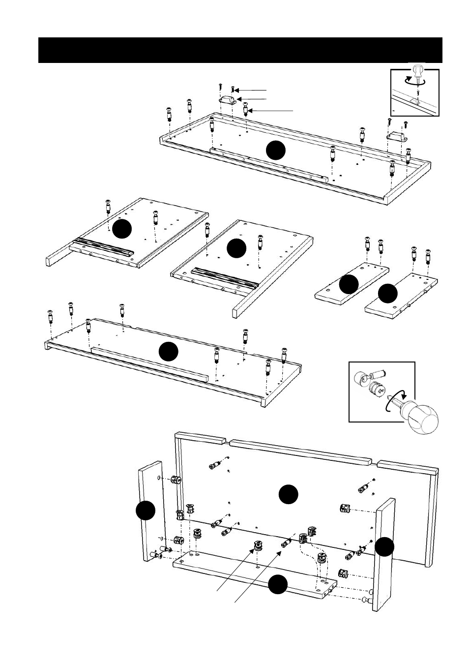
Cam Lock Screw
Cam Lock
G
F
(Figure 2)
STEP 1
STEP 2
Assembly Instructions 2/5
A
Cam Lock Screw
Insert Cam Lock Screws
into the pre-drilled
holes of Base (I).
Assemble Foot (F),
(G) and (H) with
Cam Locks
(see Figure 2).
Attach Foot unit to
Base (I) with Cam Locks.
Wood Screw
Magnet
E
I
I
H
D
Attach 2X Magnets to
Top (A) by using
Wood Screws
in the pre-drilled holes
(see Figure 1).
Insert Cam Lock Screws into the
pre-drilled holes of Top (A), Middle Panels (D), (E),
Feet (F), (G) and Base (I) with Cam Lock Screws.
Figure 1
F
G