Bradford White PDX2-75T6FSX User Manual
Page 16
16
Venting continued-
TABLE 2 - VENT CONNECTOR LENGTHS
FOR 3” (7.6 cm) DIAMETER PVC
Total # of 90° elbows
(Intake + Exhaust)
Maximum # of feet of straight pipe
(Intake + Exhaust)
2 70
(21.3 m)
3 65
(19.8 m)
4 60
(18.3 m)
5 55
(16.8 m)
6 50
(15.2 m)
7 45
(13.7 m)
8 40
(12.2 m)
TABLE 3 - VENT CONNECTOR LENGTHS
FOR 4” (10.1 cm) DIAMETER PVC
Total # of 90° elbows
(Intake + Exhaust)
Maximum # of feet of straight pipe
(Intake + Exhaust)
2 140
(42.7 m)
3 135
(41.1 m)
4 130
(39.6 m)
5 125
(38.1 m)
6 120
(36.6 m)
7 115
(35.1 m)
8 110
(33.5 m)
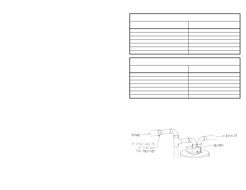
NOTE: When using 4” (10.1 cm) PVC, use a 4” (10.1 cm) to 3” (7.6 cm) reducer on
the intake of the “Tee” as shown in Figure 5. When exiting the building wall, use
another 4” (10.1 cm) to 3” (7.6 cm) reducer, and exit the wall with 3” (7.6 cm) PVC.
If the length of 3” (7.6 cm) PVC needed to go the through wall is greater then 14”
(35.5 cm), use 4” (10.1 cm) PVC to go through the wall and reduce to 3” (7.6 cm)
PVC immediately after exiting the outside wall. Terminate the venting with the 3”
(7.6 cm) vent terminals supplied, as shown in Figure 8.
Figure 5