Wine-Mate DS Series User Manual
Page 22
- 21 -
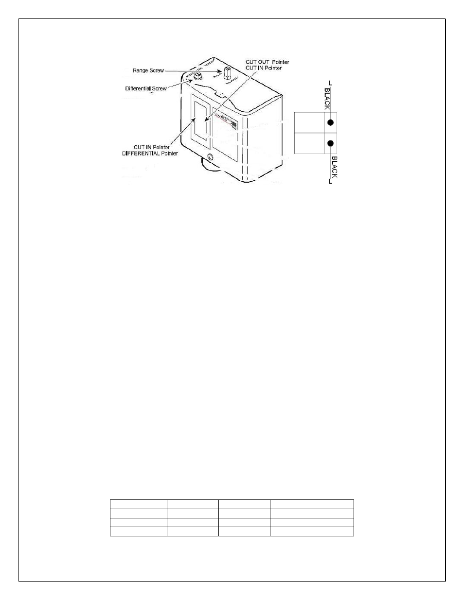
Fig. 10 Condenser Fan Cycle Control
B.
Use of the crankcase heater
The crankcase heater is installed around the lower part of the compressor and
shall be turned on all the time. The heater is self-regulated.
3. Refrigeration Piping and Leak Testing
NOTES:
• The line connection sizes of liquid filter & indicator, the valve
connection sizes of condensing unit and the line connection sizes of
evaporator unit are not necessary the same as the listed refrigeration
line sizes.
• If the condensing unit is installed above the evaporator unit, use the
suction line one listed size smaller.
• Expansion and solenoid valves have been installed on the liquid line in
the evaporator unit.
1) The installation order starts from condensing unit (including receiver and
discharge valve), liquid line filter-drier, moisture-liquid indicator, liquid line, to
evaporator unit (including liquid line connection, solenoid valve, expansion
valve, and suction line connection), returning to insulated suction line, suction
valve and then back to condensing unit.
2) Use inverted U trap to prevent liquid from flooding back to the compressor.
3) Complete pipe brazing, check solenoid valve and expansion valve restrictions
and test leak
The line sizes and refrigerant charges are listed as follows.
Model No
Liquid Line
Suction Line
Recommended Charge
WM-4500DS
1/4" OD
1/2” OD
R134a/26 OZ
WM-6500DS
1/4" OD
1/2” OD
R134a/32 OZ
WM-8500DS
3/8" OD
5/8” OD
R134a/40 OZ