Vintage Cellars Thru Wall Fan User Manual
Page 2
4.
Use a small sharp pin or very small drill bit (1/32“ or smaller) to punch
or drill these three marks to the outside of the other wall.
5.
Place the other sleeve, with grille attached, against the outside of the
wall and center its location using the three markers that you have
made, then trace the outside of the sleeve with a pencil. Cut the
circular opening with a small drywall saw. Cut inside the pencil line.
Take care not to damage the edge of the drywall. You will be installing
drywall anchors close to the hole to mount the grille.
6.
Insert the metal sleeve with grille into the cutout opening (fan output
side) and snug the flange up against the wall material, making sure
that power cord is hanging straight down.
7.
Insert the other metal sleeve into the cutout opening (fan suction side)
and snug the flange up against the wall material.
8.
Position the unattached plastic grille over the metal sleeve that was
just inserted so that the logo is at the bottom and that one of the
mounting holes is in the top center. Mark the location of all 3 wall
anchors. Make sure that the grille ribs are nicely square with the floor.
9.
Mark the position for the wall anchors on the grille.
10. Remove metal sleeve with grille attached and drill the holes on both
sides of the wall for the anchors with a sharp 3/16“ drill bit. Install wall
anchors and after re-inserting metal sleeve with grille attached, screw
the grilles down snugly. (Figure 4) DO NOT OVERTIGHTEN.
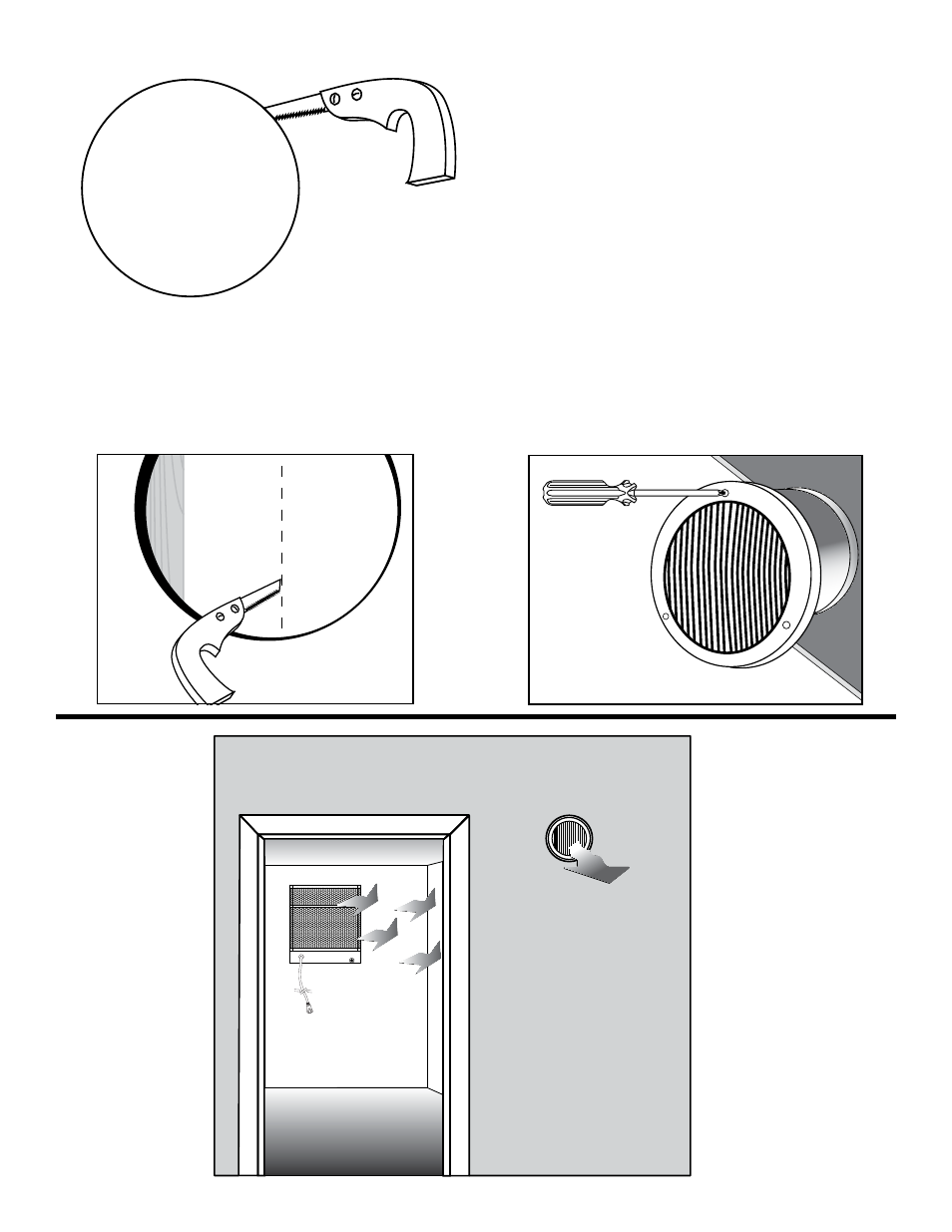
2.
Cut out the circular opening with a small drywall saw. Cut inside the pen-
cil line. Take care not to damage the edge of the drywall since you will be
installing drywall anchors close to the hole to mount the grille. (Figure 2)
3.
Project the edge of the cutout onto the inside of the other wall board in
three places, approximately 120° apart. Use a small square or a piece of
cardboard that has an exact 90° angle to mark the cutout points on the
inside of the other wall. The two circular openings must be accurately
aligned. (Figure 3)
Back of Unit
EXHAUST ROOM
HEAT
HEAT
HEAT
Figure 2
Figure 3
Figure 4