Trf-ge1 panel descriptions – Universal Remote Control (URS) MRX-2 7.11.14 User Manual
Page 5
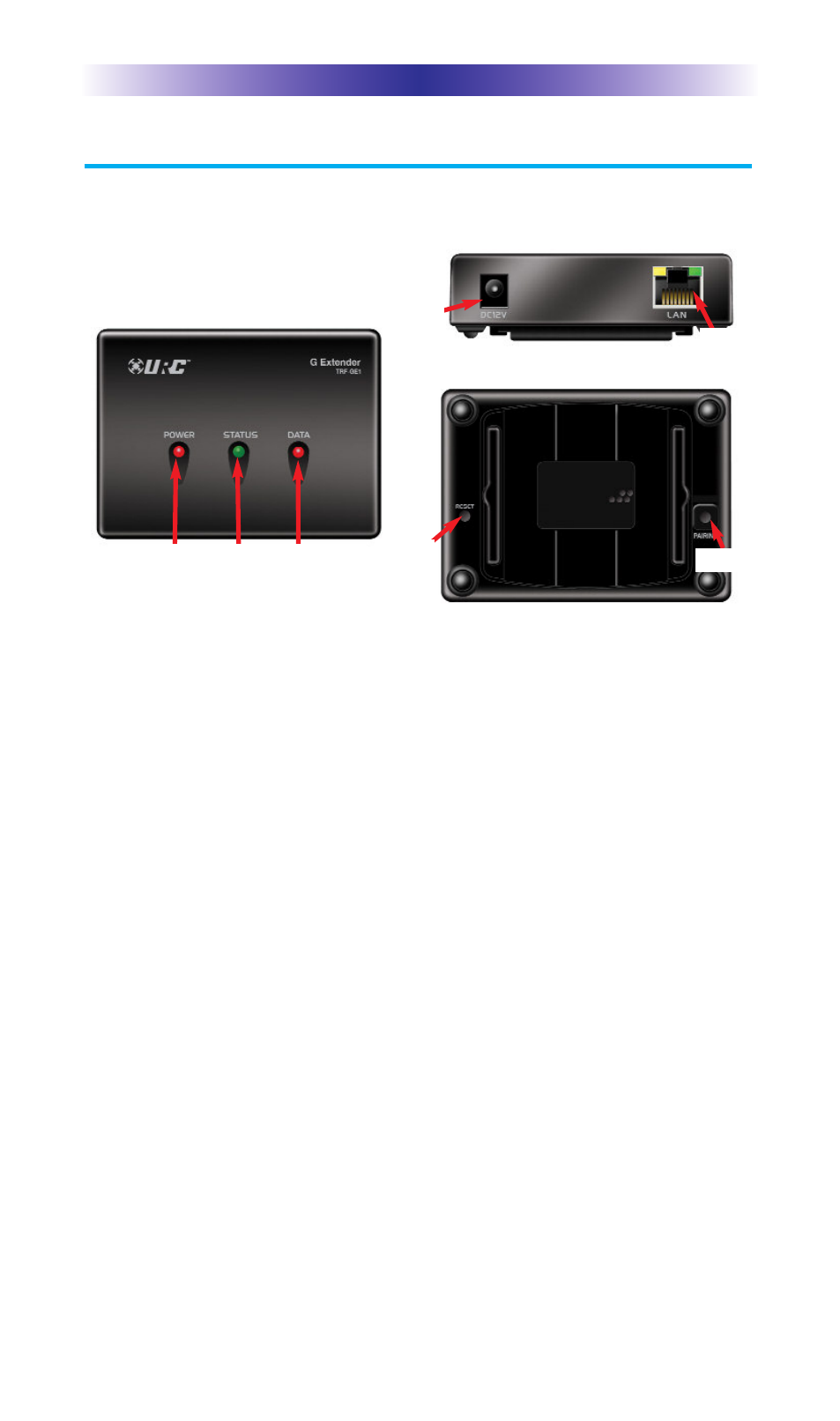
TRF-GE1 Panel Descriptions
The front, rear and bottom panel consists of:
Power LED: When illuminated this light indicates the TRF-GE1 is ON.
Status LED: The Status LED signifies when the TRF-GE1 is connected to
the network:
l
Connected: Illuminates green.
l
Not Connected: Remains OFF.
Data LED: The Data LED flashes as the TRF-GE1 receives and
transmits data.
DC 12V (1A): Plug in the included AC/DC adapter to power up the
TRF-GE1.
LAN: Communicate over the network to an MRX-20 using an
Ethernet cable.
Reset: Pressing the Reset button, with a stylus or paper clip, refreshes
the TRF-GE1. Unplugging and re-plugging the power cable also
resets the unit.
Pressing and holding the Reset button for 10 seconds, factory defaults
the TRF-GE1 and places the unit back to its original factory condition.
Page 2
TRF-GE1 G E
XTENDER
POWER
LED
STATUS
LED
DATA
LED
DC 12V
LAN
Reset
Pairing