Symtech HBA 5 With Line Laser User Manual
Page 8
8
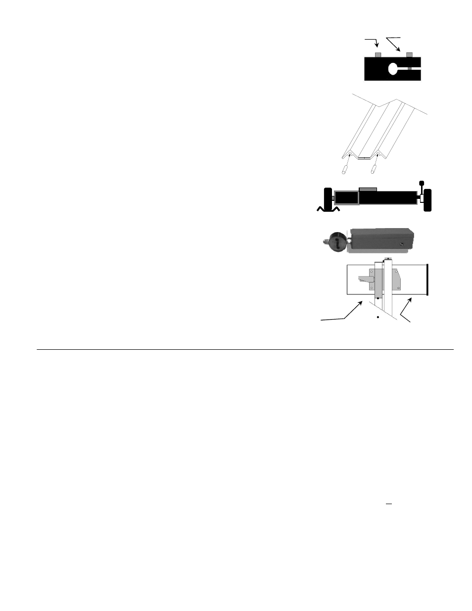
2.4.3 WHEELS TO WHEELBASE MOUNTING
There are three wheels on the wheelbase. Two wheels have an axle block that allows them to fit inside the
wheelbase, and be adjusted. Each axle block has two bolts, one for mounting to the wheelbase, and a second for
clamping the wheel axle into the block. The eccentric wheel is installed on the right leg of the wheelbase. The
straight shaft wheel is applied to the left leg of the wheelbase. The slope adjustment wheel is applied to the rear
leg Of the Wheelbase.
2.5 FLOOR RAIL
The floor rails are provided for guiding the horizontal movement of the wheelbase along the floor before the
vehicle. The floor rails assure that the alignment of the wheelbase to the vehicle does not change when moving
from lamp to lamp. The rails are attached together by using 1/4” dowel pins. Permanent attachment can be
accomplished by simply placing a couple of drops of locktite to each dowel pin before mating rails.
2.5.1 FLOOR RAIL OPERATIONS
It is recommended that the floor rail be positioned no further than 20 inches +/- 3 inches from the face of the
headlamp lens, and perpendicular to the centerline of the vehicle. The wheelbase’s two front wheels are placed
in the valley of the rail, and the rear wheel can be adjusted to conform to the floor slope of the work bay.
The floor rail is shipped in two 4-foot lengths. Included with the rails are two 1/4” dowel pins.
To assemble, slide the rail with dowel pins in the end of the rail with the arrow, and over the pins until the
edges are flush. The two pieces should hold each other firmly with no loose movement.
NOTE: If attachment of rail guide to floor is desired it will be necessary to drill holes on each end
of the rail into the working surface to accept anchoring devices.
2.6 VEHICLE POSITIONING LINE LASER
The vehicle-positioning LINE LASER is used by the operator as a guide in positioning the
HBA 5 perpendicular to the vehicle headlamp. The line laser projects a line laser on the
vehicle, which serves as an eyesight guide in aligning the vehicle.
Tension of rotation of line laser assembly should be snug, but loose enough
to allow the laser assembly to turn. NOTE: Line laser is programed to turn
off automatically after approximately 5 minutes.
2.7 ALIGNMENT HEAD & MAST
The alignment head is attached to the mast by the glide plate. The head fastens to the glide
plate by four 1/4-20 x 1/2 Button Head Cap Screws.
3.0 OPERATING PROCEDURE
3.1 ALIGNMENT PREPARATION
Certain preparations must be made prior to beginning the alignment process.
1.
The alignment area floor should be clean and clear of any unusual objects that could distort the position of the vehicle or the HBA 5
itself.
2.
The vehicle should be free of any ice or mud, in and around, the fenders and headlamps. The vehicle should not have any suspension
problems, bad shocks, springs, or struts causing the vehicle to sag or dip to any one side.
3.
The vehicle’s tires should not be noticeably deflated
4.
There should be no unnecessary or heavy loads inside the vehicle except for the driver.
5.
The headlamps should be cleaned, including any reflective areas around the lenses. The alignment head lens should also be free of
any dirt or dust.
6.
The headlamp should be checked for burnouts, or condensation inside the lamp. If condensation is present, replacement of the lamp
assembly is recommended.
7.
Before setting floor slope, head should be set level using the level vial mounted on the aim screen. Move HBA5 to a known level
surface, and proceed in leveling the head. Adjust the head level (left to right) by loosening and adjusting front eccentric axle until
bubble appears in center of level vial. Re-tighten axle and confirm level of head. You are now ready to set your floor slope.
3.2 FLOOR SLOPE ALIGNMENT
The floor slope adjustment must be performed to align the alignment head parallel with the slope of the floor. Improper floor
slope adjustment will result in improper headlamp alignment. NOTE: Floor rail must be used during floor slope adjustment IF
floor rail is used during headlamp alignment procedure.
3.2.1 POSITIONING THE ALIGNMENT HEAD TO THE FLOOR SLOPE
1.
Position HBA 5 in front of vehicle with front wheels in floor rail and approximately one foot outside of vehicle.
2.
Lower the alignment head to lowest possible position.
3.
Adjust the alignment head until level vial is centered. (This is for a starting position only)
Mounting
Bolt
Wheel tightening
Bolt
Alignment
Head
Glide Plate