Assembly – Symtech BCA 4 User Manual
Page 4
4
2. ASSEMBLY
Inspect all components of the :BCA 4
ISOColor system to assure that no damage has occurred during shipment, compare
contents of package with that of the exploded view to make sure that no component has been inadvertently left out of
packaging. If a component is missing, contact our customer service department at 888-884-8182 for an immediate
replacement.
2.1 BASE / WHEEL ATTACHMENT
Place base of system on floor, or table with channel facing
downward.
Front of Base
Insert a
5
/
16
” x 5
1
/
2
” carriage bolt into each of the holes noted,
making sure that the square carriage bolt head seats securely into the
square hole placement.
Complete wheel assembly by placing in order a large nylon washer,
wheel, small nylon washer and self-locking
5
/
16
” nut on carriage
bolt.
Tighten self-locking nut snug against wheel, but not so tight as to
hinder free wheel movement.
Insert floor slope eccentric and wheel into mounting block on base
(rear wheel). Tighten friction bolt until floor slope eccentric can be
moved, but not loose enough to move by itself.
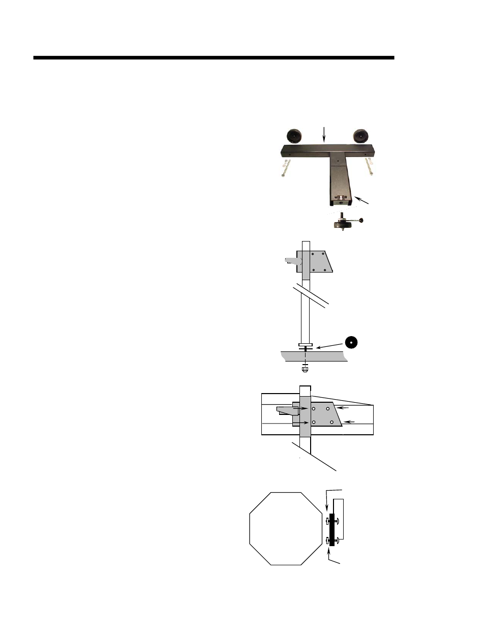
2.2 MAST / GLIDE PLATE / ROTATIONAL MAST MOUNT
The Mast and Glide Plate are packaged as an assembly.
Place rotation bearing over mast stud and insert rotational mast stud
into base. Secure mast to base with
3
/
8
” flat washer and
3
/
8
” self-
locking nut. Tighten nut securely then back-off
1
/
8
turn, or until
mast rotates freely with minor resistance.
Move glide plate up and down the mast through its full motion, by
depressing handle.
2.3 OPTICAL ALIGNMENT HEAD
Remove optical alignment head from shipping carton.
Inspect for any damage that may have occurred during
shipment i.e. lens, case, etc..
Attach optical alignment head to the mast glide plate by
aligning mounting holes of glide plate with the holes in
the optical head. Insert ¼” x 20 x ¾” phillips machine
screw through glide plate, place a ¼” x
1
/
8
” (WHITE)
nylon spacer on each upper attachment screw, place a ¼”
x
3
/
16
” (BLACK) nylon spacer on each lower attachment
screw and tighten securely.
Remove protective paper covering from viewing window
on top of optical head.
Move optical head through the full range of movement to
assure of smooth operation.
2.4 SIGHTING UNIT
Sighting unit is the “L” bracket assembly enclosed
in the accessories box.
NOTE: Mount sighting unit so that unit is
located directly over the optical head.
Insert the
5
/
16
” x 2.5” phillips head machine screw
with
5
/
16
” nylon washer into the sighting unit.
Tighten
this Bolt
Glide
Plate
Optical
Head
¼” x
1
/
8
”
Nylon Spacers
(WHITE)
¼” x
3
/
16
”
Nylon Spacers
(BLACK)
ROTATIONAL
BEARING
¼” x 20 x ¾”
Phillips Machine Screw