Bussmann, Power module, Switch ps – Cooper Bussmann Power Module PS User Manual
Page 3: All-in-one module
Bussmann
®
Power Module
™
Switch
PS
All-In-One Module
Form No. PS
Page 3 of 5
BIF Doc# 1145
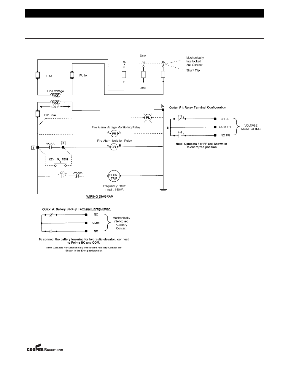
Typical Control with Wiring Options for Fire Safety Interface (Option R1)
Legend:
N.O.F.A. – Normally Open Fire Alarm contacts supplied from the fire alarm system to initiate the shunt trip.
Shunt Trip – Solenoid for remote trip of switch, which is activated by the closing of the fire alarm contacts or key test switch.
Option R1 – Fire Safety Interface Relay that is operated at 120VAC from secondary of transformer. No additional power needed.
CR – Control Relay used to isolate the N.O.F.A. contacts from the duty of the shunt trip.
FR – Fire Alarm Voltage Monitoring Relay used to monitor presence of voltage in switch from a remote location (i.e. Fire Alarm Control Panel).
PL – Pilot Light to visually indicate presence of voltage on outside of switch enclosure.
CPT – Control Power Transformer used to step down line voltage to 120VAC to power shunt trip coil.
SW Aux. – Normally closed contact when switch is closed. Opens as power switch opens.
Key Test – Key-to-Test switch used to operate shunt trip from the outside of switch enclosure. Can be used for trouble-shooting and inspection.
Mechanically Interlocked Auxiliary Contact – Contact used to disconnect secondary source of power.
■ – Terminal Block Connection Point.
● – Pre-wired Connection Points.
Bussmann
®
8-29-01
XXXXXX