Side panel – QOMO QD3900 User Manual
Page 10
9
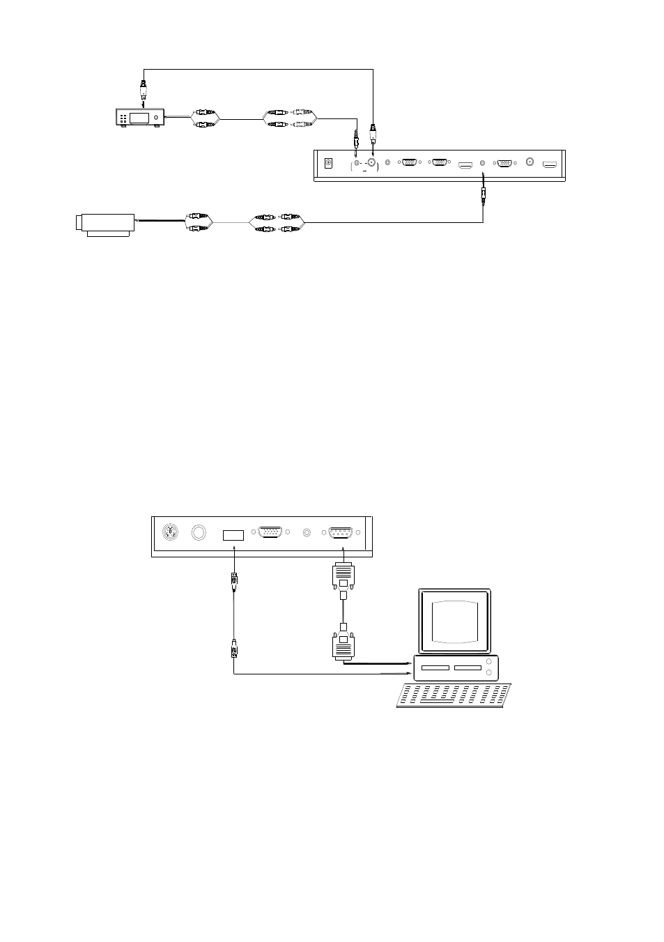
Step 5: Connect to the video equipment with Video input.
1
2
3
4
6
7
8
5
DC 12V IN
VIDEO
IN
AUDIO
AUDIO IN COMPUTER IN
PROJECTOR
COMPUTER OUT HDMI IN AUDIO OUT
VIDEO OUT HDMI OUT
9
10
11
Rear Panel
Video equipment
Video out
Audio out
Audio input
(or amplifier/speaker equipment)
Projector
Video Cable
4
In the step 2, the connection between the C-Video output signals to the
projector was established, where the RGB cable runs from the visualizer
and goes to the projector. Once the connections have been made as
detailed in the steps 2,3,4,5, input signals from the HD equipment,
computer, visualizer camera, and C-Video are going to the RGB1 input on
the projector and will be displayed on the projector screen as RGB1. These
signals can be seen in turn when pressing “CAM/PC1/PC2” and
“HDMI/VIDEO” on the control panel of the visualizer.
Step 6: Connections for external control from the computer.
RS232
AUDIO IN
RGB IN
MIC
PROJECTOR
USB
Side Panel
RS-232 cable
USB cable
of the computer
of the computer
USB connector
RS 232 connector
Use the computer RS232 cable (9-pin to 9-pin) to make the connections
displayed below to control the visualizer from an external computer.
A USB connection enables the computer to capture still images and/or
video streams from the visualizer. Special software is required for this
operation.
4. Turn on the power by pressing the
“POWER” button.