5table 1a — physical data (si) – Carrier 48TFE008-014 User Manual
Page 5
5
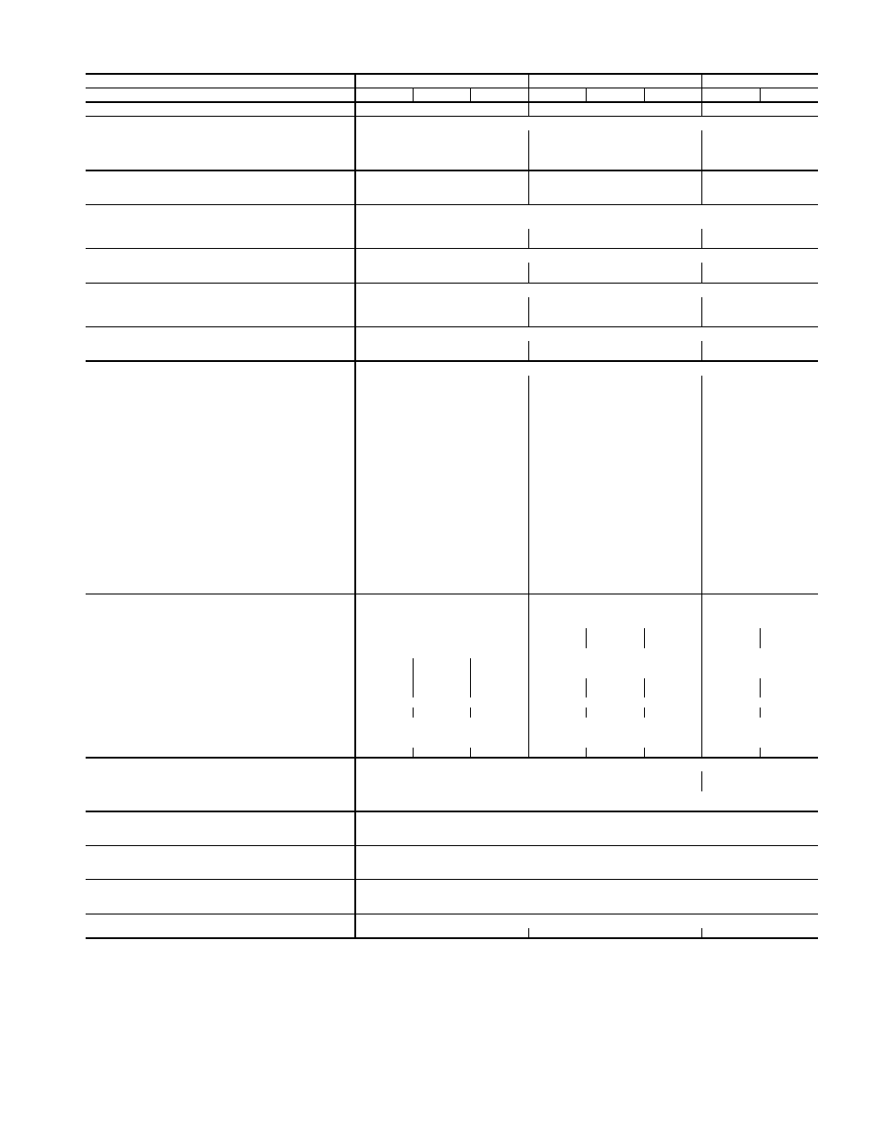
Table 1A — Physical Data (SI)
LEGEND
*Weight of 356 mm (14-in.) roof curb.
NOTE: The 48TF units have a loss-of-charge (low pressure) switch located in
the liquid line.
UNIT SIZE 48TF
008
012
014
Low Heat (D), Medium Heat (E), High Heat (F)
D
E
F
D
E
F
D
E
NOMINAL CAPACITY (kW)
21.5
29.2
35.9
OPERATING WEIGHT (kg)
Unit
395
469
476
Durablade Economizer
20
20
20
EconoMi$er
28
28
28
Roof Curb*
65
65
65
COMPRESSOR TYPE
Hermetic
Hermetic
Scroll
Quantity
2
2
2
Oil (ml)
1479 ea
1479 ea
1597 ea
REFRIGERANT TYPE
R-22
Operating Charge (kg)
Circuit 1
2.10
3.08
3.49
Circuit 2
2.22
3.22
3.49
CONDENSER COIL
Enhanced Copper Tubes, Aluminum Lanced Fins
Rows...Fins/m
1...669
2...669
2...669
Total Face Area (sq m)
1.90
1.92
2.30
CONDENSER FAN
Propeller Type
Nominal L/s
2880
3050
3050
Quantity...Diameter (mm)
2...559
2...559
2...559
Motor BkW...r/s
.19...15.5
.19...15.5
.19...15.5
EVAPORATOR COIL
Enhanced Copper Tubes, Aluminum Double-Wavy Fins, Acutrol™ Feed Device
Rows...Fins/m
3...590
3...590
4...590
Total Face Area (sq m)
0.74
0.93
1.03
EVAPORATOR FAN
Centrifugal Type
Quantity...Size (mm x mm)
1...381 x 381
1...381 x 381
1...381 x 381
Type Drive
Belt
Belt
Belt
Nominal L/s
1230
1700
1980
Motor kW
1.12
1.50
2.24
Maximum Continuous BkW
1.79
1.79
2.76
Motor Frame Size
56
56
56
Fan r/s Range
8.2-11.7
9.5-13.0
12.0-15.0
Motor Bearing Type
Ball
Ball
Ball
Maximum Allowable r/s
26.7
26.7
26.7
Motor Pulley Pitch Diameter Min/Max (mm)
61/86
71/97
102/127
Nominal Motor Shaft Diameter (mm)
16
16
22
Fan Pulley Pitch Diameter (mm)
178
178
203
Nominal Fan Shaft Diameter (mm)
25
25
25
Belt, Quantity...Type...Length (mm)
1...A...1245
1...A...1245
1...A...1346
Pulley Center Line Distance (mm)
425-489
403-445
403-445
Speed Change per Full Turn of
Movable Pulley Flange (r/s)
.70
.70
.60
Movable Pulley Maximum Full Turns
From Closed Position
5
5
5
Factory Setting
5
5
5
Factory Speed Setting (r/s)
8.2
9.5
12.0
Fan Shaft Diameter at Pulley (mm)
25
25
25
FURNACE SECTION
Rollout Switch Cutout Temp (C)
90.6
90.6
90.6
Burner Orifice Diameter (mm)
Natural Gas
— Std
3.05
3.05
3.05
3.28
3.05
3.28
Liquid Propane — Alt
2.44
2.44
2.44
2.59
2.44
2.59
Thermostat Heat Anticipator Setting (amps)
400 v
Stage 1
.14
.14
.14
.14
.14
Stage 2
.14
.20
.20
.20
.20
Gas Input (kW)
Stage 1
21.1
31.9
39.8
31.9
39.8
43.9
39.8
43.9
Stage 2
31.4
50.4
59.8
50.4
59.8
65.6
59.8
65.6
Efficiency (Steady State) (%)
80
80
80
Temperature Rise Range (C)
–6-10
2-18
7-24
2-18
7-24
4-21
7-24
4-21
Manifold Pressure (kPa)
Natural Gas
— Std
8.3
8.3
8.3
Liquid Propane — Alt
8.3
8.3
8.3
Field Gas Connection Size (mm)
13
19
19
19
19
19
19
19
HIGH-PRESSURE SWITCH (kPa)
Standard Compressor
Internal Relief (Differential)
3103 ± 345
3448 ± 345
Cutout
2951
Reset (Auto.)
2206
LOW-PRESSURE SWITCH (kPa)
Cutout
48 ± 21
Reset (Auto.)
152 ± 48
FREEZE PROTECTION THERMOSTAT
Opens (C)
–1 ± 3
Closes (C)
7 ± 3
OUTDOOR-AIR INLET SCREENS
Cleanable
Quantity...Size (mm)
1...508 x 635 x 25
1...406 x 635 x 25
RETURN-AIR FILTERS
Throwaway
Quantity...Size (mm)
4...406 x 508 x 51
4...508 x 508 x 51
4...508 x 508 x 51
Bhp —
Brake Horsepower
BkW —
Fan Input Watts x Motor Efficiency