Interfaces, 1 power supply input, Jp12 – Kontron CP3-BP2-PB-RIO User Manual
Page 6: Jp11, Pd15: cp3-bp2-pb-rio cpci backplane
PD15: CP3-BP2-PB-RIO
CPCI Backplane
Page 6
© 2003 PEP Modular Computers GmbH
RID 24229 PD15, Rev. 01
5.
Interfaces
5.1
Power Supply Input
The V1 ... V4 output voltages from the power supply unit to the backplane are connected via
power bar elements to the respective supply terminals of the power distribution backplane and
the CP3-BP2-PB-RIO backplane. The power bars themselves are specifically designed to fit
the backplane raster and allow additional backplanes to be integrated into a customized
designed system to satisfy almost any application requirements.
5.2
System Monitor and Control Connectors JP11 and JP12
This backplane is provided with two connectors for system monitor and control signal interfac-
ing to external devices. Both are 26-contact, male, double pin-row connectors, and have the
same signal pinout configuration. The system management bus (IPMB0), the power supply
monitor and control signals, and push button reset (PRST#) signal are all implemented on
these connectors.
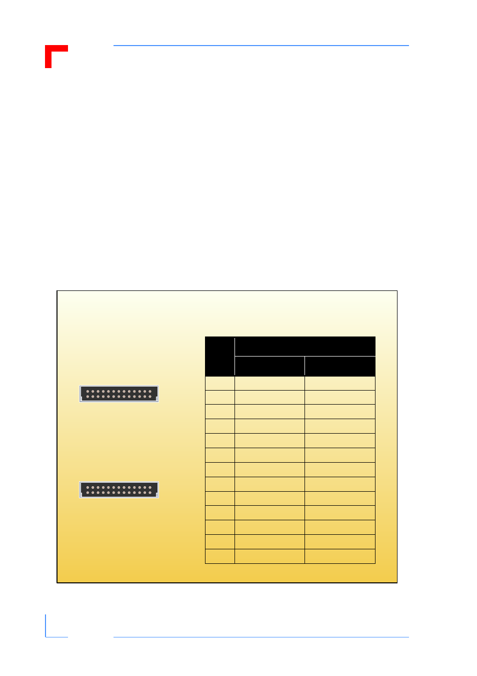
Figure 4: Orientation and Pinout of the CP3-BP2-PB-RIO SMC Connectors JP11 and JP12
1
13
b
a
JP12
1
13
b
a
JP11
Table 2: Pinout of CP3-BP8-P47-RIO
SMC Connectors JP11 and JP12
Pin
Function
Pin Row A
Pin Row B
1
IMPB0_SCL
GND
2
IMPB0_SDA
IMPB0_PWR
3
N/C
GND
4
N/C
GND
5
N/C
GND
6
INH#
GND
7
FAL#
DEG#
8
PRST#
GND
9
GND
V1 SENSE (+5V)
10
V2 SENSE (+3.3V)
SENSE RTN
11
V3 SENSE (+12V)
GND
12
V1 SHARE (+5V)
V2 SHARE (+3.3V)
13
V3 SHARE (+12V)
GND