Kontron 820155 DC-DC User Manual
Page 7
820155 DC-DC Supply 10-32Vin 90W
KTD-00740-C
Public User Manual
Date: 2008-04-24 Page
7 of 9
AMP (J6)
The AMP connector can be used to remotely mute Audio Amplifiers etc. the first 4 seconds after PSU is
turned on. In general the AMP is not required to mute the motherboard audio system when the motherboard is
booting. In stead the BIOS can silence the speaker system.
The RMT signal is unconnected the first 4 seconds after PSU turns on and then it is connected to Vin.
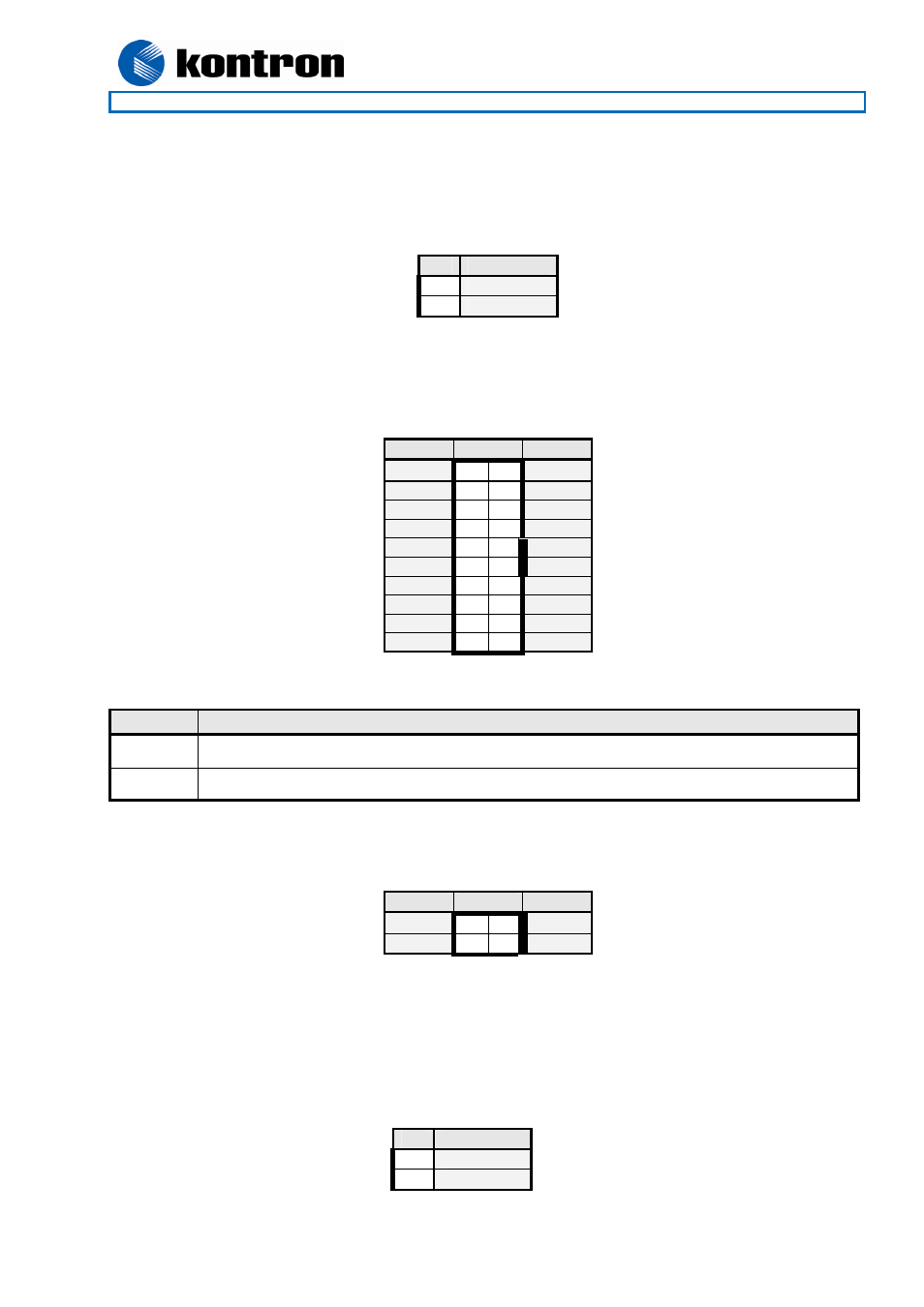
ATX Connector (J7) ATX Power connector 20 pin (Molex P/N 39-01-2200).
Signal
PIN
Signal
+12V 10
20
5V
SB5V 9 19
5V
P_OK 8 18
nc
GND 7
17
GND
5V 6
16
GND
GND 5
15
GND
5V 4
14
PSON#
GND 3
13
GND
3V3 2
12
-12V
3V3 1
11
3V3
Control signal description:
Signal
Description
P_OK
Active high output signal indicating that the +12V, +5V and 3V3 are within operating limits.
PS_ON#
Active low input signal to turn on the power supply outputs.
ATX+12V Power Connector (J2)
Signal
PIN
Signal
GND 1 3
+12V
GND 2 4
+12V
Note 1: Use of the 4-pin ATX+12V Power Connector is required for operation of the KT690mITX and 986LCD-
M boards.
LED (J5) Connect a standard LED, no resistor required, to implement a “Power ON LED”. This option can be
used instead of using a +3.3VSB power output on Motherboard Front Panel connector. When the PSU is used
in Battery Driven Application Mode and when in State 2c, then the LED is flashing every 2 seconds.
Pin
Signal
1
Gnd
2
RMT
Pin
Signal
1
LED -
2
LED +