1 introduction, 1 board overview, 2 board diagrams – Kontron CPS3410 User Manual
Page 6: 1 functional block diagram, Introduction, Board overview, Board diagrams, Functional block diagram, Cps3410 functional block diagram, 1 board over view
D R A F T — F O R I N
T E R N A L U S E O N L Y
6
www.kontron.com
User Guide
CPS3410
1 Introduction
1.1 Board Over view
The CPS3410 is a 3U CompactPCI® Serial board providing four Gigabit Ethernet interfaces via RJ-45
connectors on the front panel. All four interfaces are controlled by the Intel® I350 Ethernet control-
ler, which is connected to the backplane via one x4 PCI Express® 2.1 link. The Intel® I350 Ethernet
controller provides a powerful set of features that include I/O virtualization and QoS features, Energy
Efficient Ethernet (EEE), as well as support for Jumbo Frames (up to 9.5 KB) and PXE boot option. On
top of that, the Intel® Advanced Network Services (ANS) software package adds support for Adapter
Teaming, Load Balancing or 802.1q VLANs.
1.2 Board Diagrams
The following diagrams provide additional information concerning board functionality and component
layout.
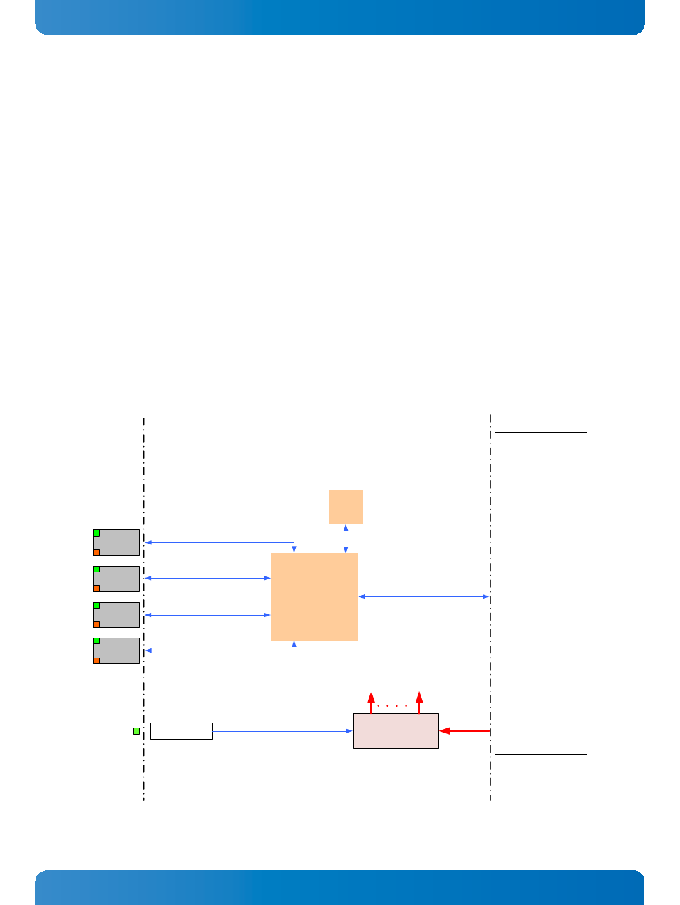
1.2.1 Functional Block Diagram
Figure 1: CPS3410 Functional Block Diagram
Front
CompactPCI
Serial
Onboard Power Supplies
12 V
x4 PCIe 2.1
PCIe
Flash
Intel® I350
Quad GbE Controller
P6
optional,
for mechanical stability
P1
Hot Swap Handle
Power Enable
Pwr LED
RJ-45 + Mag.
RJ-45 + Mag.
RJ-45 + Mag.
RJ-45 + Mag.
4x GbE