FBT WMS 406 EN User Manual
Page 3
I
UK
INTRODUZIONE
INTRODUCTION
Fig. 1
Fig. 2
Fig. 3a
Fig. 3b
Il diffusore a cassetta
WMS 406 T/EN è formato da un corpo in lamiera
verniciata a polvere ed utilizza un altoparlante (Ø 130 mm) con un’estesa
gamma di risposta. È dotato di un trasformatore per linee a tensione costante
(50, 70 e 100 V). Questi diffusori sono stati appositamente sviluppati per
essere impiegati in sistemi d’emergenza e d’evacuazione: sono infatti
dotati di morsettiera ceramica e di fusibile termico, che garantiscono la
salvaguardia della linea di collegamento altoparlanti nel caso in cui un
possibile incendio metta fuori uso uno o più diffusori ad essa collegati.
The
WMS 406 T/EN box-type speaker unit consists of a powder-painted
metal housing and uses a loudspeaker (Ø 130 mm) with a broad response
range. It has a transformer for constant-voltage lines (50, 70 and 100 V).
These speaker units have been developed specifically for use in emergency
and evacuation systems and each has its own ceramic terminal strip
and thermal fuse. These ensure the protection of the line connecting the
loudspeakers if a fire puts one or more of the speaker units connected to it
out of use.
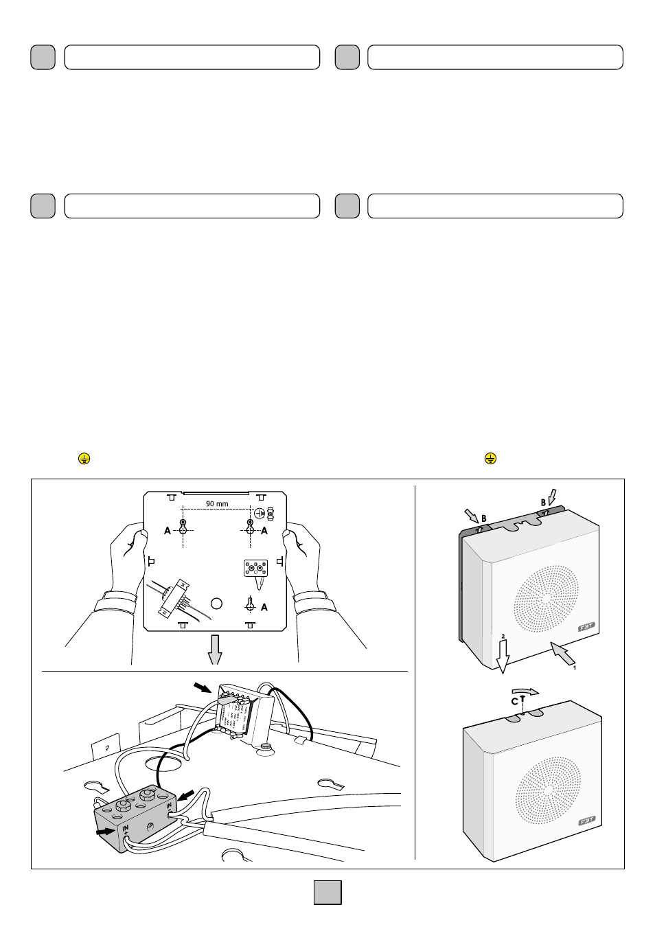
1. Tenendo come riferimento la piastra posteriore, praticare almeno due
dei tre fori (A) indicati in fig. 1 e fissarvi tasselli e viti adeguati;
2. Inserire la piastra sulle viti e collegare l’altoparlante e la linea di
distribuzione (fig. 2).
3. Appoggiare la parte frontale del diffusore sui ganci (B) e spingere verso
il basso fino al bloccaggio completo; fissare poi la vite (C) fornita in
dotazione al diffusore nella parte superiore (fig. 3).
I diffusori
WMS 406 T/EN devono essere collegati in derivazione alla linea
di distribuzione, assicurandosi che la potenza complessiva assorbita dai
diffusori non ecceda quella massima fornita dall’amplificatore (in fig. 4 è
mostrato un collegamento alla linea 100V).
La potenza dei diffusori è impostata in fabbrica per linea 100V/6W. Nel
caso si volesse modificare questa impostazione, è possibile cambiare la
potenza di uscita tramite l’apposito terminale ad inserzione rapida facendo
riferimento alla targhetta posta sul trasformatore (vedi fig. 2).
1. Using the rear panel for reference purposes, drill at least two of the
three holes (A) shown in Fig. 1 and secure suitable anchor bolts and
screws to them;
2. Fit the panel onto the screws and connect the loudspeaker and the
distribution line (Fig. 2).
3. Place the front part of the speaker unit on the hooks (B) and push
downwards until it is fully locked in place. Then secure the screw (C)
included in the supply to the speaker unit at the top (Fig. 3).
WMS 406 T/EN speaker units must be connected to the distribution line
by branching them, making sure that the overall output absorbed by the
speaker units does not exceed the maximum output supplied by the
amplifier (Fig. 4 shows a connection to the 100V line).
The power of the speaker units is factory-set for a 100V/6W line. If you wish
to change this setting, it is possible to alter the output power by means of
the quick-fit terminal provided for this purpose, consulting the data plate on
the transformer (see Fig. 2).
I
UK
INSTALLAZIONE E CONNESSIONE
INSTALLATION AND CONNECTION
NOTA: Per la connessione di terra è presente un’apposita vite, evidenziata
dal simbolo
NOTE: A screw is provided on the rear of the speaker unit for connecting
to earth. It is indicated by the symbol