Introduzione introduction, Installazione installation, Manutenzione maintenance – FBT MHO 420 EN User Manual
Page 3
I
UK
INTRODUZIONE
INTRODUCTION
NOTA: Per la connessione di terra è presente un’apposita vite, evidenziata
dal simbolo .
NOTE: A screw is provided on the rear of the speaker unit for connecting to
earth. It is indicated by the symbol
I
UK
INSTALLAZIONE
INSTALLATION
I diffusori sonori a tromba
MHO 420 TW/EN sono caratterizzati da un
corpo in alluminio e da staffe orientabili in acciaio inossidabile. Il tipo di
costruzione ed i materiali utilizzati ne permettono l’uso anche in esterno o
in ambienti particolarmete umidi (es.: piscine). Questi diffusori sono stati
appositamente sviluppati per essere impiegati in sistemi d’emergenza
e d’evacuazione: sono infatti dotati di morsettiera ceramica e di fusibile
termico, che garantiscono la salvaguardia della linea di collegamento
altoparlanti nel caso in cui un possibile incendio metta fuori uso uno o più
diffusori ad essa collegati.
The
MHO 420 TW/EN horn-type speaker unit features an aluminium housing
and swivelling stainless steel brackets. The type of construction and the
materialsused are such that they can be used outdoorsand in particularly
damp environments(swimming-pools, etc.). These speaker units have been
developed specifically for use in emergency and evacuation systems and
each has its own ceramic terminal strip and thermal fuse. These ensure the
protection of the line connecting the loudspeakers if a fire puts one or more
of the speaker units connected to it out of use.
INSTRUCTIONS AND ADvICE FOR MOUNTING
For safety reasons, it is advisable to pay special attention when securing
the speakers to the structure used to support it (wall, ceiling, stake, cross-
member, etc.).
• Keep a distance of at least 2 to 3 metres from the listening point.
• Secure the speakers to a particularly strong wall, using expansion bolts
large enough to bear the weight of the horn and suitable for the type of
surface. If securing to a panel use nuts and bolts with a diameter of at
least 5 mm.
• Direct the horns towards the area to be covered, consulting the polar
diagram.
• In the event of outdoor mounting, always point the mouth of the horn
downwards.
ISTRUZIONI E CONSIGLI PER IL MONTAGGIO
È consigliabile, per motivi di sicurezza, porre particolare cura nella
connessione a terra del telaio e nel fissaggio dei diffusori alla struttura
portante (parete, soffitto, palina, traversino, ecc.).
• Mantenere una distanza minima dal punto di ascolto almeno di 2/3
metri.
• Fissare i diffusori ad una parete robusta utilizzando tasselli ad espansione
adeguati al peso della tromba e al tipo di supporto; nel caso di fissaggio
ad un pannello utilizzare dadi e bulloni con diametro minimo di 5 mm.
• Orientare i diffusori verso l’area da sonorizzare facendo riferimento ai
diagrammi polari.
• In caso di montaggio in esterno, rivolgere sempre la bocca della tromba
verso il basso.
I
UK
CONNESSIONI E REGOLAZIONI
CONNECTIONS AND ADJUSTMENTS
Careful attention should be required for the polarity.
For the voltage and power, which are to be used, please refer to the
relevant label on the rear side of the diffuser. In any case, please check
that the absorbed power by the diffusers, which are connected to the line,
is equal or lower to the nominal power supplied by the amplifier.
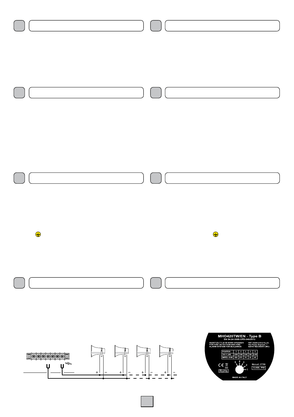
• Connect the ends of the cable leading out from the horn to the 100 V
distribution line (see Fig. 1).
Si raccomanda di porre particolare attenzione alla polarità.
Fare riferimento, per la potenza che si desidera impiegare, ai collegamenti
riportati nelle targhetta posta sul lato posteriore della tromba. Verificare, in
ogni caso, che la potenza assorbita dai diffusori collegati alla linea sia uguale
o inferiore alla potenza nominale erogabile dall’amplificatore utilizzato.
• Collegare le terminazioni del cavo uscente dal diffusore alla linea di
distribuzione 100 V (vedi fig. 1).
AMPLIFIER
SUPPLY VOLTAGE
POWER CONSUMPTION
POWER RATING
0
8
50V 70V 100V
BIANCO
WHITE
NERO
BLACK
BLU
BLUE
NERO
BLACK
TRX20-TW
TRX20-V
Fig. 1
Fig. 2
The change of the power value can be simply carried out by means of the
relative 5-position trimmer located on the rear side of the horn (det. A, Fig. 2).
Insert a little flat-blade screwdriver into the slot and turn it clockwise or anti-
clockwise until the reference mark matches the desired power. The position/
power correlation is indicated in tabel (B).
Il cambio di potenza può essere effettuato operando sull’apposito
regolatore a 5 posizioni (part. A, fig. 2) presente sul lato posteriore del
diffusore. Inserire un piccolo cacciavite a lama piatta nella cava e ruotare
in senso orario od antiorario fino a che il segno di riferimento non indica la
potenza desiderata. La correlazione posizione/potenza sono indicate nella
tabella (B).
I
UK
MANUTENZIONE
MAINTENANCE
Check periodically the tightness of the screws securing the bracket of the
horn and those of the wall-mounting system of same.
Also check the condition of the connecting cables and remove any excess
dust or waste deposited by the wind or by insects. Do not use substances
capable of corroding (e.g. alcohol, solvents, petroleum, etc.) to clean the
speakers.
Verificare periodicamente il serraggio delle viti di fermo della staffa del
diffusore e quelle del sistema di fissaggio a muro della stessa.
Verificare inoltre lo stato di efficienza dei cavi di collegamento e rimuovere
l’eventuale eccesso di polvere o detriti depositati dal vento o dagli insetti.
Non utilizzare per la pulizia dei diffusori sostanze corrosive come: alcool,
solvente, benzina, etc.
A
B