ETS-Lindgren 3301B Active Rod & Field Antenna (Archived) User Manual
Page 24
24
| Power
Circuitry
The battery charger is protected against overcurrent by a 200 mA 250 VAC
time-delay fuse. If it becomes necessary to replace the fuse, use a fuse of the
same type and rating to maintain safe operations. The fuse is accessible by
removing the two Phillips head screws on the underside of the unit. The output of
the battery charger is protected against overcurrent conditions by use of
fold-back circuitry.
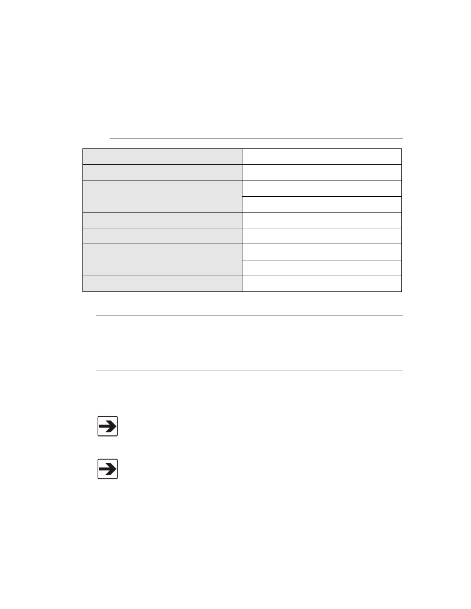
7.1.2 Specifications
Input voltage:
115/230 VAC selectable
Input frequency:
50/60 Hz
Input power:
20 VA max
Protection class:
Class II double insulated
Input fuse rating:
200 mA time-delay type 5 x 20 mm
Input power connection:
IEC-320 power inlet
Output voltage:
12 VDC (13.5-15 VDC)
Output current:
350 mA
Safety approvals:
TUV, CSA
7.2 Battery Low Indicator
If the Battery Low/Power On indicator on the front of the unit does not illuminate
when the power switch is on, the batteries should be recharged.
7.3 Fuses
Located inside the Model 3301B are two fuses, one for each battery. To replace
the fuses:
Disconnect the power cord and charger before opening the unit.
Replace the fuses with either Type AC size 0.5 AMP fast acting, or
5 x 20 mm fuses.
1. Use a Phillips head screwdriver to carefully remove the screws around
the edge of the bottom panel. Lift the bottom panel off the unit.
Archived 3/18/10