Of f – ETS-Lindgren 3301B Active Rod & Field Antenna (Archived) User Manual
Page 21
Principles of Operation
|
21
The antenna rod terminal is directly connected to the high
impedance gate of a field effect transistor. Do not lift the
antenna by the rod or touch it before properly grounding out
to the unit case. Accumulated static charge on test personnel
may damage the FET. If the antenna is used in a location
where static discharges are likely to be prevalent, attach a
grounding clip between the chassis and the antenna rod
while the antenna is being set up to prevent damage to the
amplifier circuitry.
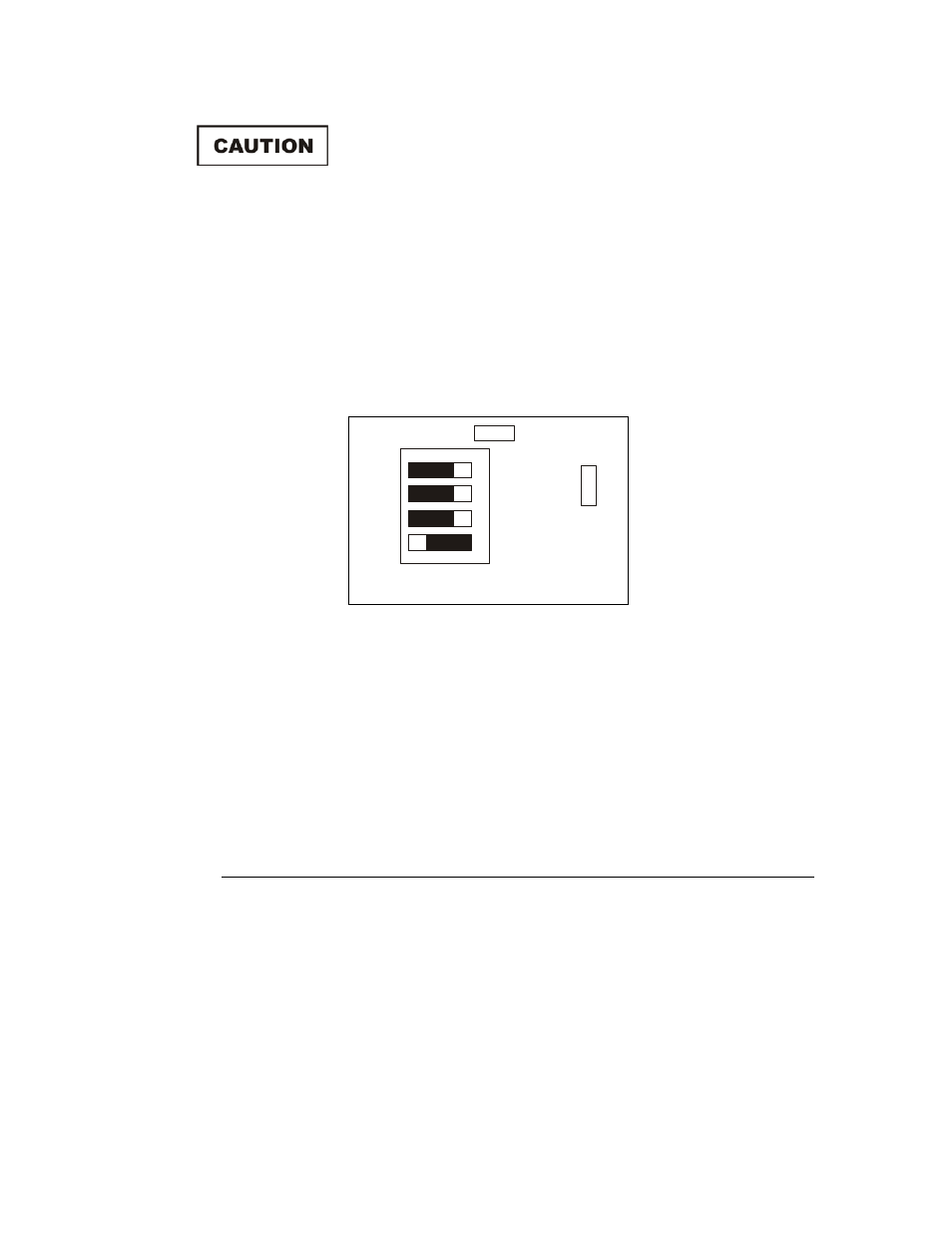
The following diagram reflects the sequence of functions as they are connected
on the board.
10 dB (+/- 10%) Input Attenuator
30 dB (+/- 10%) Input Attenuator
1.9 kHz Low Frequency Roll Off
22.0 kHz Low Frequency Roll Off
Moving any switch to the extreme left, toward the center of the unit, activates the
indicated function. Moving the switch to the extreme right, toward the side of the
unit, deactivates that function. The most commonly used configuration will have
the 22 kHz roll off switch on and all other options off.
6.3.1 Factory Settings
The unit comes configured from the factory with the 22.0 kHz LF Roll Off set to
on. All other switches are off.
It is anticipated that the unit will normally be used with one of the roll off switches
on. Due to the abundance of low frequency ambient noise, in most settings using
the full bandwidth of the unit will make it very susceptible to saturation. However,
when extremely low frequency measurements are required, the unit is capable of
providing these measurements.
FR
O
N
T
P
A
N
E
L
ON
22.0 kHz
LF Roll Off
1.9 kHz
LF Roll Off
30 dB
Atten.
10 dB
Atten.
OF
F
FU
S
E
FUSE
Archived 3/18/10