EFCO Duracast Pressure Plate User Manual
Page 8
EFCO CORPORATION 6/2012 PART NO. YW45
8
Duracast Pressure Plate Installation Instructions
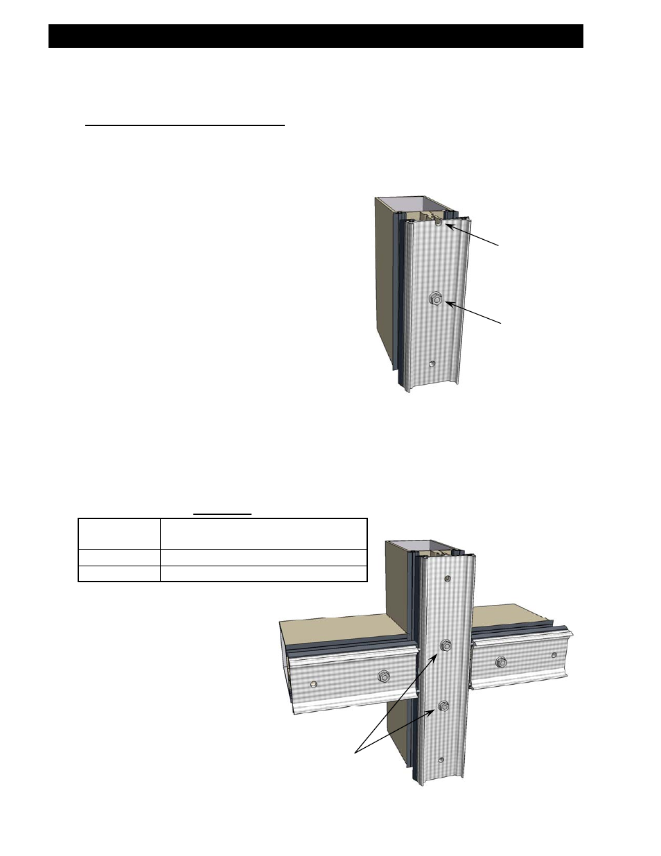
STEP #4 Install Pressure Plate
A. First attach the vertical pressure plates and then the horizontal pressure
plates into position using stainless steel hex washer head screws (refer to
Table #1 for screw size based on Curtain Wall Series). Locate screws in
the first complete pre-punched hole
on each end of the pressure plate no
more than 3.5” from the end. Refer
to the final approved shop drawings
for screw spacing.
B. Torque screws to 80 inch-pounds.
C. In cold Weather, first torque all
pressure plate screws to 40 inch-
pounds. Once all four sides have
been clamped down, torque all
screws to 80 inch-pounds.
D. When possible, work from the center
outward on horizontals and from the
sill upward on verticals.
E. Glazier should always place screws in
pre-punched holes immediately above and below each horizontal. This will
provide maximum control of pressure on mullion plugs that provide a criti-
cal sealing function.
F. The pressure plate should extend 3” past any splice (see Section IV:
Vertical Splice Joints).
Section III: Pressure Plate Installation
Pressure Plate End
Incomplete Hole
Hex washer head
screw in first
complete hole
(see Table #1).
Place screws in holes
immediately above and
below all horizontals
Table #1
Curtain Wall
Series
Screw Size & Type
5600
#13 x 5/8" S.S. Hex Washer Head Screw
5900
¼" x 1" S.S. Hex Washer Head Screw