Operation – Code 3 Motorcycle Sirens 3951, 3955 User Manual
Page 7
6
Audio Adjustments
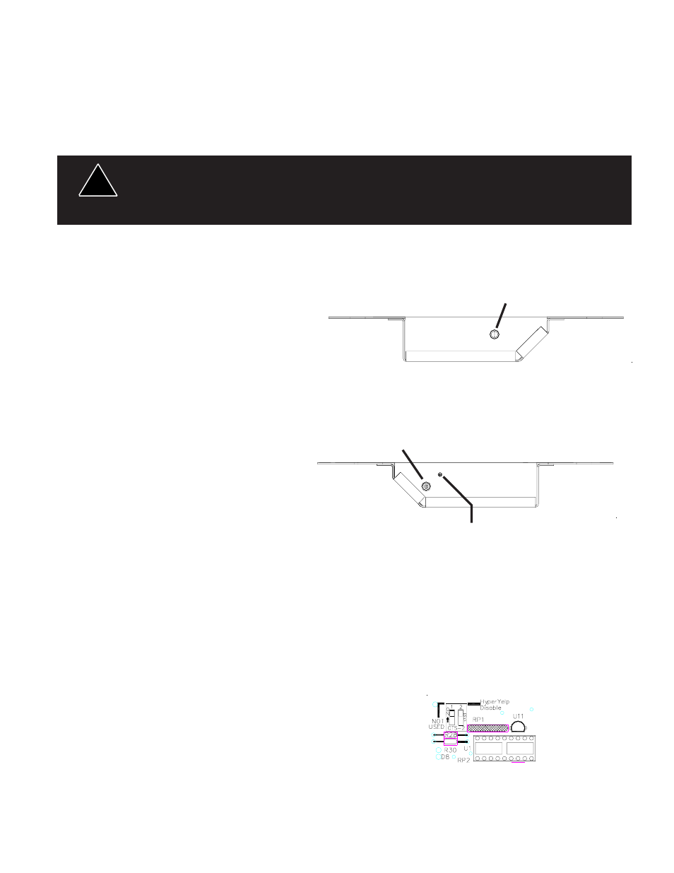
Maximum Radio Rebroadcast (RRB) Adjustment - This trimmer (located on the rear of the siren) sets the
maximum level that the 2-way radio will reach with the front panel VOLUME control in the fully clockwise
position. To adjust properly, set the 2-way radio volume control to produce normal radio volume from the 2-
way radio speaker or headset. Set the RRB switch to the on position to enable the RRB function. Next set
the siren's front panel VOLUME control knob fully clockwise and adjust the rear panel RRB trimmer to produce
the desired volume from the siren speaker.
Maximum P.A. Volume Adjustment - This trimmer ( located on the front panel next to the volume control
knob) sets the maximum level that the P.A.
volume will reach with the front panel
VOLUME control in the fully clockwise
position. To adjust properly, set the front panel
volume control fully clockwise. While keying
the microphone hold the microphone close to
your lips and speak directly into it in a normal
voice and adjust the trimmer until the
maximum volume out of the speaker is
intelligible and produces no feedback. Set the
front panel volume control for the desired PA
volume and install all screws and fastners.
Configuration Switches
HyperYelp Disable Switch - Switch DS1 is
shown in Figure 3. When switch 2 on DS1 is
switched to the ON position, the HyperYelp
tone is disabled. Switch 1 is not used.
Operation
SCROLL, Momentary Push-button Switch - Each time the SCROLL button is pressed it causes the siren to
scroll up one tone. Starting from the OFF mode, pressing the SCROLL button will cause the siren to start
producing the WAIL tone. Pressing the button again will cause the siren to switch to YELP mode. Pressing
the button again will cause the siren to switch to HyperYelp mode. Pressing the button a fourth time will cause
the siren to switch back to WAIL mode. This process may be repeated as often as desired.
WAIL, Latching Switch - Produces the Wail tone continuously while this switch is in the ON position.
Figure 2 - Adjustments
MAXIMUM PA Adjustment
Front View
Rear View
MAXIMUM RRB
Adjustment
Volume
Control
Figure 3 -
Configuration
Switches
Any electronic device may create or be affected by electromagnetic interference. After
installation of any electronic device, operate all equipment simultaneously to insure
that operation is free of interference.
WARNING!
!