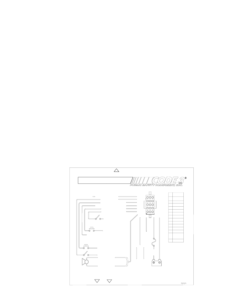
Set-up and adjustment, Model 3951 siren wiring diagram, Figure 1 – Code 3 Motorcycle Sirens 3951, 3955 User Manual
Page 6
5
1 2 3
4
5 6
7
8 9
10 11 12
13 14 15
PIN FUNCTION
1
SPK1
2
SPK2
3
IGNITION
4
+12VDC
5
GROUND
6
SCROLL
7
INTERCLR
8
AIRHORN
9
RRB1
10
RRB2
11
WAIL
12
RRB ENBL
13
MIC HI
14
MIC LO
15
PA PTT
14AWGRED
+12VDC
10A*
FUSE
IGNITION
SWITCHED
+12VDC
100W
SIREN
SPEAKER
14AWG
SCROLL
INPUT
+12VDC
MODEL 3951 SIREN WIRING DIAGRAM
14AWG
INTERCLEAR OUTPUT
AIRHORN INPUT
INTERCLEAR, 1A MAX
AIRHORN SWITCH
18AWG
AUDIO INPUT FROM
2-WAY RADIO
SCROLL
SWITCH
USE CODE 3 POWER BOOSTER KIT (P/N INTBS)
FOR MORE THAN 1A ON INTERCLEAR OUTPUT
MAXIMUM RRB AUDIO ADJUSTMENT
*USERMUST SUPPLYEXTERNAL10AFUSE IN +12VDCPOWER WIRE
14AWG
BLK,
GROUND
(EARTH)
RRB
+12VDC
VOLUME CONTROL
MAXIMUMPA LEVELADJUSTMENT
USER INTERFACE
+12VDC
WAILSWITCH
PA
MIC
RRB ENABLE
+ 12VDC
WAIL INPUT
11
6
7
8
12
1-2
9-10
3
4
5
13-14-15
Code 3, Inc., a subsidiary of
Public Safety Equipment, Inc.
RRB SWITCH
Figure 1
- NEG (Ground) - Connect (14 AWG wire) to the negative terminal of the battery. This supplies
ground (earth) to the siren.
SCROLL- SCROLL switch input . Circuit is configured to accept positive signals only.
InterClear
®
- Connect to the device or circuit that is to be activated by the InterClear feature. The
InterClear circuit is internally current limited at 1 Amp. Should your requirements require higher
currents, use the InterClear Power Booster Kit (# INTBS), available from your Code 3
®
supplier.
AIRHORN - AIRHORN switch input . Circuit is configured to accept positive signals only.
RRB - RRB Audio Input. Connects to the two-way radio speaker.
WAIL - WAIL switch input . This switch should be a rocker type switch which maintains it's position
until switched OFF by the user. This circuit is configured to accept positive signals only.
RRB ENABLE - switch input . This switch should be a rocker type switch which maintains is position
until switched OFF by the user. Circuit is configured to accept positive signals only.
Microphone High - MIC HI signal from the user supplied, common microphone interface.
Microphone Low - MIC LO signal from the user supplied, common microphone interface.
PA PTT - PTT signal from the user supplied common microphone interface.
Set-Up and Adjustment
The only adjustments necessary for the 3951 series sirens are Maximum P.A. Adjustment (accessible from
the front of the unit), and Maximum RRB Adjustment (accessible from the rear of the unit). Refer to Figure 2
for the location of these adjustments. Make these adjustments prior to securing the unit .