Code 3 Scorpion Siren User Manual
Page 5
5
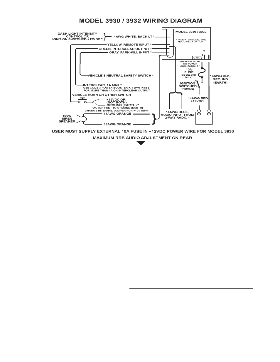
YELLOW - REMOTE - Remote switch (Horn ring or foot switch). Circuit can be configured for both
ground (earth) or positive signals. Unit is configured at the factory to operate from a ground (earth)
signal. See page 6 for details on configuring for a +12V input.
WHITE - BACKLIGHTING - Provides +12V to siren backlighting. Connect to a vehicle circuit that is
powered when the ignition switch is " on ". If backlighting dimming is desired, connect to the dash
lights' circuit. Caution- If connected to the battery the backlighting will be active at all times.
GRAY - PARK KILL- This feature automatically deactivates siren tones when the vehicle is shifted into
PARK. Siren tones will be disabled until the vehicle is shifted out of PARK. This circuit is activated
by a negative signal. Connect this input to a circuit that is GROUNDED (Earth) when the vehicle is
shifted into PARK. It is the installer's responsibility to determine an appropriate location in
the vehicle circuitry to connect this wire.
BLUE - RRB - Connects to the two-way radio speaker.
GREEN - InterClear
®
(Optional) - Connect to the device or circuit that is to be activated by the
InterClear feature. The InterClear circuit is internally current limited at 1 Amp. Should your
requirements require higher currents, use the InterClear Power Booster Kit (# INTBS), available
from your Code 3 supplier.
Model 3932 has 1/4" Male Quick-Connect Printed Circuit Board Terminals power connections.
Use #14 gauge wire terminated with1/4" female, fully insulated quick-connect terminals only.
RED - (+12V) - Connect (14 guage wire) to a positive +12 volt DC source. It is recommended that the
user protect this wire with a 10 Amp fuse or circuit breaker located at the source.
BLACK - NEG - Connect (14 guage wire) to the negative terminal of the battery. This supplies ground
(earth) to the siren.
Figure 2 - Wiring Diagram