Installation instructions - cont, Warning – Code 3 2005 + Impala Passenger Side User Manual
Page 4
4
Larger wires and tight connections will provide longer service life for components. For high current wires it
is highly recommended that terminal blocks or soldered connections be used with shrink tubing to protect
the connections. Do not use insulation displacement connectors (e.g. 3M
®
Scotchlock type connectors).
Route wiring using grommets and sealant when passing through compartment walls. Minimize the
number of splices to reduce voltage drop. High ambient temperatures (e.g. under hood) will significantly
reduce the current carrying capacity of wires, fuses, and circuit breakers. Use "SXL" type wire in engine
compartment. All wiring should conform to the minimum wire size and other recommendations of the
manufacturer and be protected from moving parts and hot surfaces. Looms, grommets, cable ties, and
similar installation hardware should be used to anchor and protect all wiring. Fuses or circuit breakers
should be located as close to the power takeoff points as possible and properly sized to protect the wiring
and devices. Particular attention should be paid to the location and method of making electrical connections
and splices to protect these points from corrosion and loss of conductivity. Ground terminations should
only be made to substantial chassis components, preferably directly to the vehicle battery. The user should
install a fuse sized to approximately 125% of the maximum Amp capacity in the supply line to protect
against short circuits. For example, a 30 Amp fuse should carry a maximum of 24 Amps. DO NOT USE
1/4" DIAMETER GLASS FUSES AS THEY ARE NOT SUITABLE FOR CONTINUOUS DUTY IN SIZES
ABOVE 15 AMPS. Circuit breakers are very sensitive to high temperatures and will "false trip" when
mounted in hot environments or operated close to their capacity.
WARNING!
Installation Instructions - Cont:
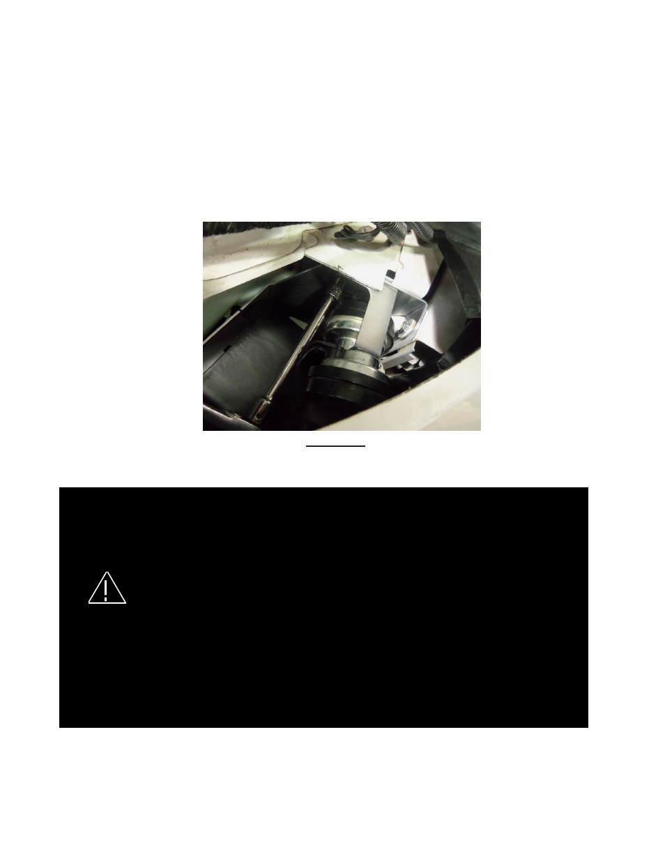
Step 10. Reconnect the wiring connector to the bottom horn. Position the New Horn Assembly with both horn flares
facing down as shown in Figure -18. Thread the supplied 1/4" X 5/8" Long Slot/Hex head sheet metal screw with a sup-
plied 1/4" internal tooth star washer through the mounting hole in the Horn Relocation/Mounting Bracket and into the
threaded hole in the vehicle's frame from Step -4. Tighten the screw using a 10 mm socket making sure that the top of
the Horn Relocation/Mounting Bracket is up against the under side of the vehicle's frame flange (see Figure -18). Posi-
tion the horns so that they aim down and slightly to the rear of the vehicle and tighten the horn retention nuts to secure
the horns in place. Note: The top and bottom horns should not be touching each other or anything around them.
Step 11. Route the speaker wires as desired. Connect the speaker leads to the siren according to the siren install
manual.
Step 12. Re install the vehicle's head light.
FIGURE -18