Alumax L-312 User Manual
Page 17
INSTALLATION MANUAL
1
17
CONTINUED
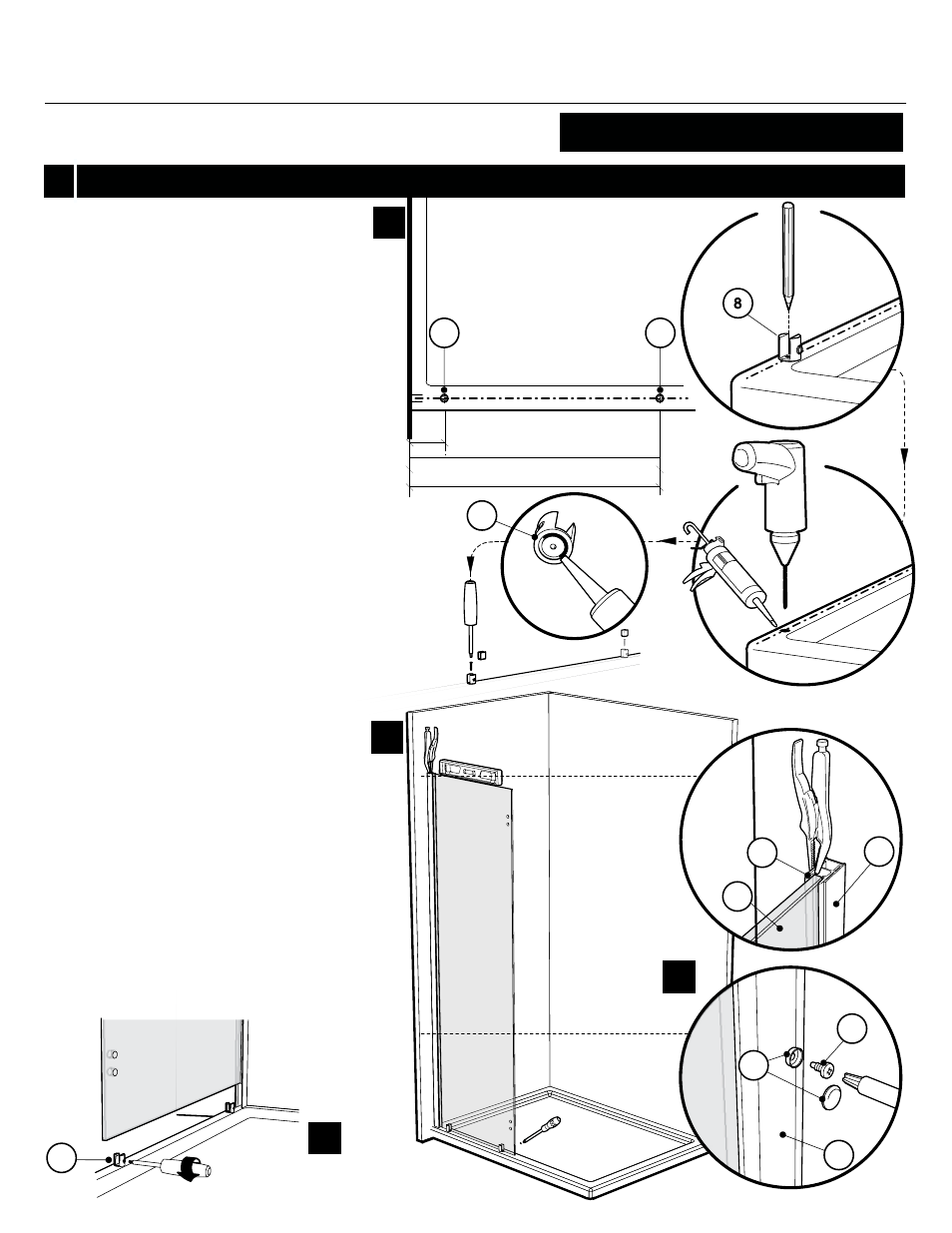
1e.
1f.
1g.
1h.
1f
1g
1e.
1h
8
3.3
3.1
5
5
2.2
2.1
11.4
3
11.2
3
5
30 3/8”(56301-56302-56303)
21”(4301-4302-4303)
4 1/4”
Place the bottom clips (5) for return panel on
the line traced previously following dimension
shown on the plan view.
Mark the screw location. Remove temporary
the bottom clips to drill the base using #1/8”
drill bit.
Put silicone onto the bottom clip bottom face
groove and around the hole. Finally, fasten the
bottom clips to the base using the provided
screws. Place the gaskets into bottom clips
slots.
Slide the return panel assembly into the wall
jamb (3) and through the bottom clips slots.
Once the return panel has been adjusted,
secure the expander (2.2) (9.1) to the wall jamb
(3) by way of a clamp so as to keep the return
panel level.
Tighten the bottom clips set screws (5).
Secure the wall jamb (3) to the expander (2.2)
(9.1) by using #8- 3/8 screws (11.2), as well as
screw caps (11.4).
5
201X, 202X, 311X, 312X, 311TBX, 312TBX